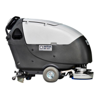
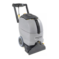
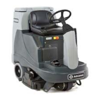
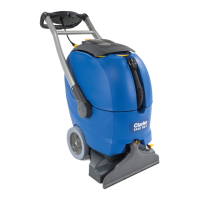
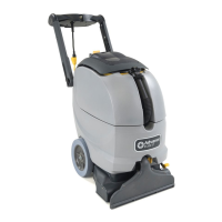
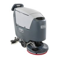
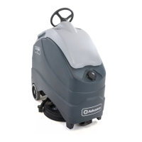
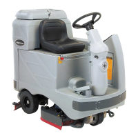
MACHINE NOMENCLATURE (For CA 451, CA 531)
Throughout this Manual you will nd numbers in brackets – for example: (2). These numbers refer to the components indicated in
these two nomenclature pages. Refer to these pages whenever you need to identify a component mentioned in the text.
Control panel1.
Handlebar2.
Water removable ller hose (optional)9.
Squeegee lifting/lowering lever10.
Deck lifting/lowering pedal11.
11a. Pedal position when deck is lifted
11b. Pedal position when deck is lowered
Rear steering wheels13.
Front wheels on xed axle14.
Squeegee vacuum hose15.
Recovery water drain hose16.
Solution drain and level check hose17.
Brush/pad-holder deck18.
Brush/pad-holder with pad19.
Solution tank20.
Recovery water tank21.
Recovery water tank cover22.
Can holder23.
Document retainer (optional)24.
Squeegee25.
Squeegee mounting handwheels26.
Squeegee balance adjusting handwheel27.
Machine straight forward movement adjusting handwheel28.
Machine forward speed adjustment handwheel29.
30a. Recovery water tank cover (opened to be cleaned)
30b. Recovery water tank cover (completely opened)
Tank cover gasket31.
Cover movable retaining plate32.
Cover xed retaining plate33.
Serial number plate/technical data/conformity certication34.
Plug for squeegee vacuum hose cleaning35.
Vacuum grid with automatic shut-off oat36.
Solution ller neck37.
Foam lter38.
Compensation hole39.
Recovery water tank (open)40.
Tank lifting handle41.
Lifted tank tie rod42.
Vacuum system motor cover43.
Vacuum system motor sound-deadening lter44.
Solution lter54.
Solution tap55.
Solenoid valve56.
Power supply cable59.
Power supply cable holder60.
Recovery water tank retaining plate61.
Brush/pad-holder switch62.
Vacuum system switch63.
Counterweight64.
Hour counter (optional)79.
Washing water ow control switches82.
82a. Flow increase switch
82b. Flow decrease switch
82c. Solution ow indicator

 Loading...


