31
SM_MC_6P Ver.2.0_2021
Function
D
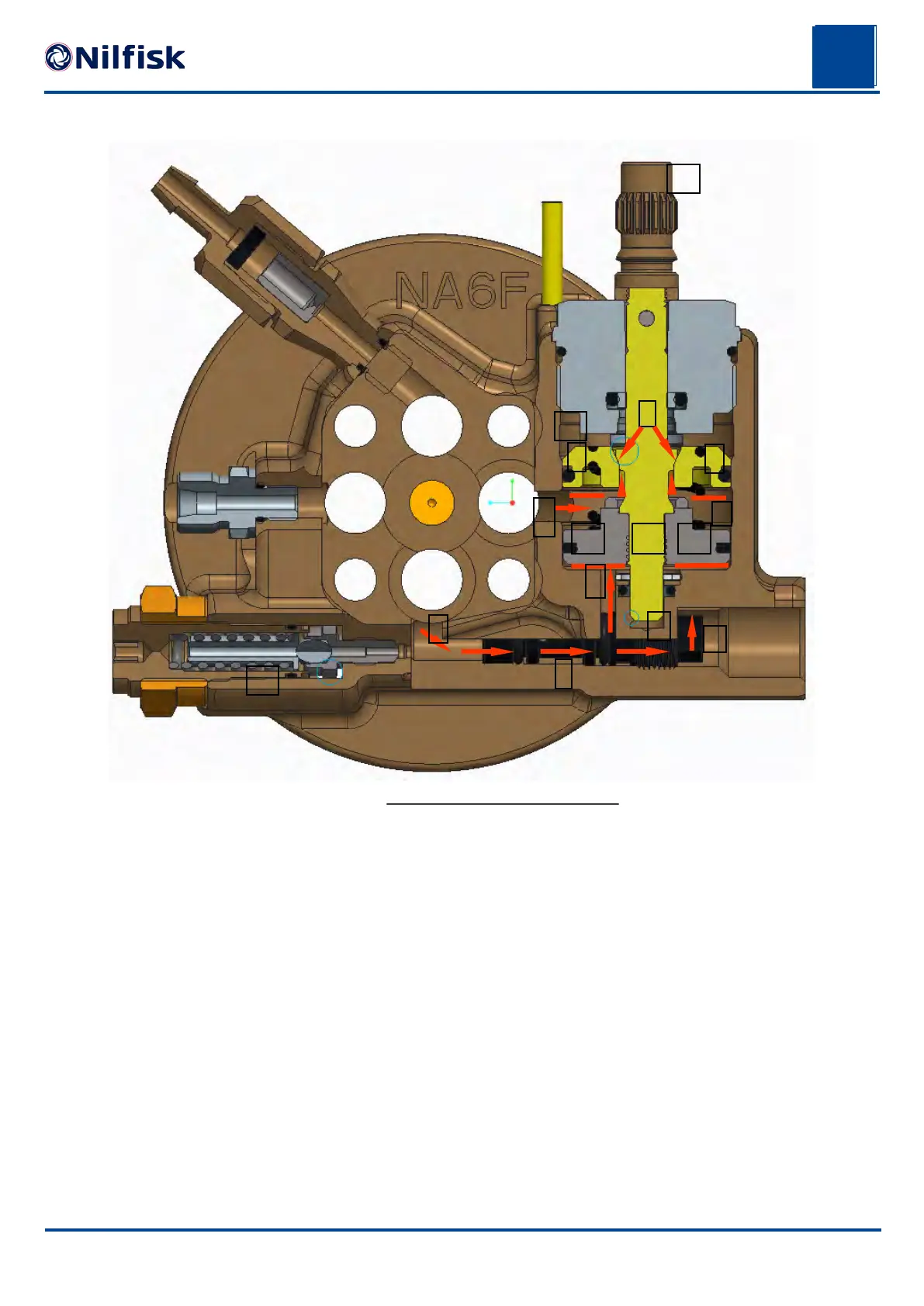
By-Pass valve system_MC 6P
By-pass valve components are shown in high pressure running mode.
The water is flowing from the 4 pump pressure valves through the channel (1) to the injector nozzle
(4) and also to the by-pass valve housing area (2 & 3) between the 2 pistons (9) and (10). Pos. (1,2,
3, 4, 5 and 6) is high pressure areas. Below the by-pass valve stem (11) there is water inlet pres-
sure in the area marked (7) as this area is connected to the pump water inlet side through a small
channel.
Area marked (8) is the valve cone and seat area. This is where the water/pressure is stopped from
flowing from the pressurized side to the pump water inlet side. When the by-pass valve is in by-pass
mode, the cone is lifted from the seat, and opens for water flow back to water inlet side. Pos. (9) is
the by-pass valve upper piston which is in a fixed position during operation. Pos. (10) is the by-pass
valve lower piston, which can move up and down. Pos. 11 is the by-pass valve stem, which can
move up and down together with piston (10). Stem (11) and piston (10) are screwed together. Pos.
(12) is the channel in which the water flows back to the water inlet side when pump is running in by-
pass.
Pos. (13) is the water volume/pressure regulator.
Pos. (14) is the safety valve.
7
6
1
2
3
4
5
8
9
10 10
9
11
12
13
14
 Loading...