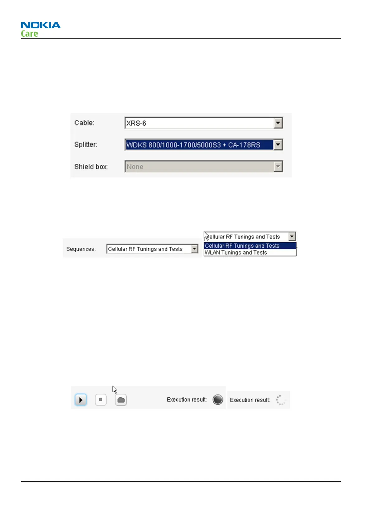
An upper part of RF Tuning Tool (RF Testing Tool too) view has controls for cables, splitters and shield boxes
defined by Nokia. A right e.g. cable must be selected because then RF Tuning has different attenuation values
for different cables, splitter and/or shield boxes. Splitter consists of splitter itself and cables to splitter (here
CA-178RS). Selections in drop down lists remains even though tool is closed and opened again so there is no
need to make selection if tuning environment remains from hardware point of view. Note that a product
specific loss in the attenuation chain comes from data package and RF Tuning summarizes all losses into one
from connection in product/module jig to instrument.
A different kind of RF tunings can be executed by RF Tuning Tool. It depends on product how many different
sequences there are. All possible tunings (sequences) are listed in Sequences drop down list (picture below,
left one). As an example (picture below, right one) product has two sequences: Cellular RF Tunings and Tests
and WLAN Tunings and Tests. Some products may have also FM TX tuning.
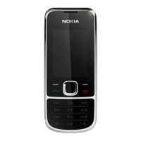
An actual execution for the sequence begins when the user clicks “play” button (picture below, button at far
left in three-button group). The execution can be stopped by clicking “stop” button (in the middle of three-
button group). It does not stop the execution immediately but an ongoing step in the sequence is ended
first. A “folder” button (at the right in three-button group) opens a window where log files, the execution
produces, are located.
A status of the execution is shown with the execution result “ball”. A status of the execution is indicated with
colors:
•
Grey – the sequence hasn't been executed yet. The ongoing execution is shown as rotating tiny balls.
•
Green –the sequence has been executed successfully.
•
Yellow – the sequence execution has been stopped and all executed steps were passed successfully.
•
Red – The execution was done but some step failed (e.g. limit fail), or the execution stopped due the fail
or the execution was stopped and some step in already executed steps failed.
All steps in the sequence are shown in the sequence view (below). The progress of the execution is shown
with the status indicators (balls): grey with arrow – the execution of step is ongoing, green – step passed
successfully and red – step failed.
RM-761; RM-799; RM-800
RF Troubleshooting
Page 4 – 46 COMPANY CONFIDENTIAL Issue 1
Copyright © 2011 Nokia. All rights reserved.