Key component placement
Please refer to the L1/L2 Service Schematics.
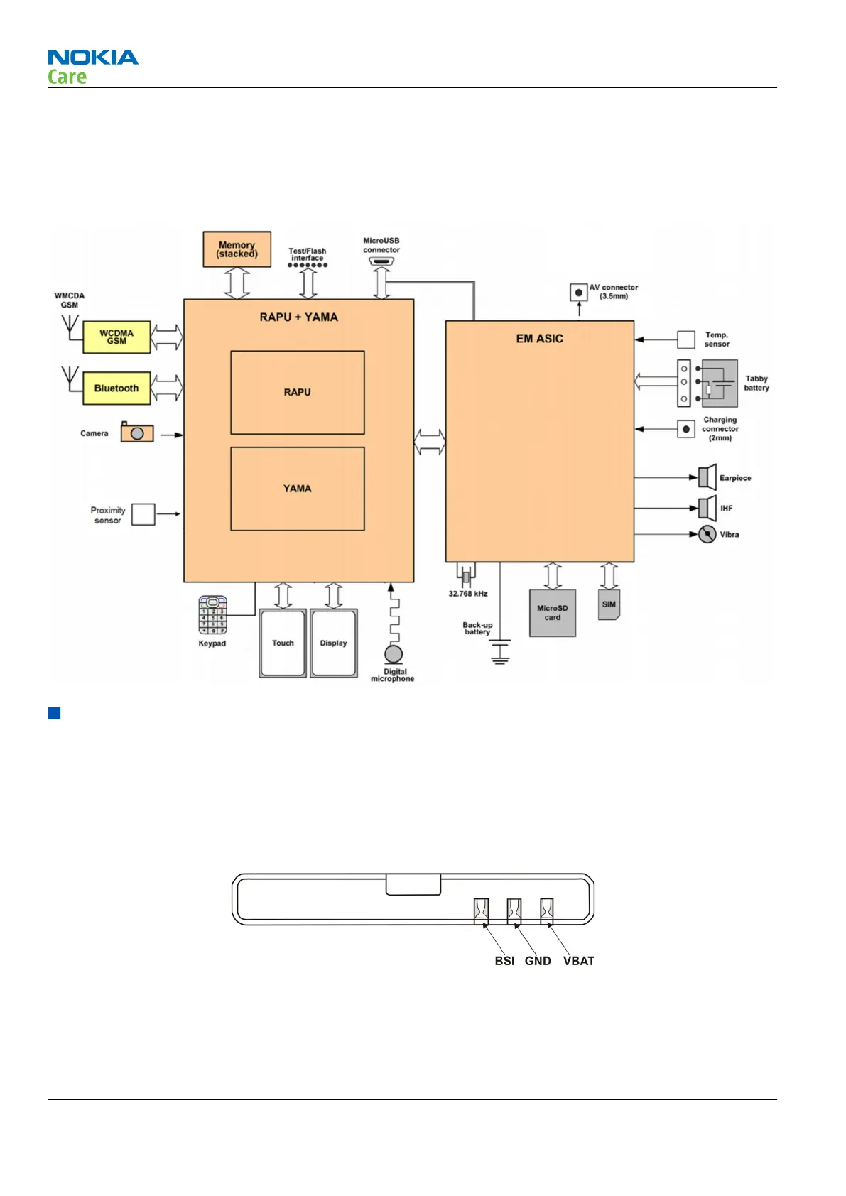
System module block diagram
Energy management
Battery and charging
Battery
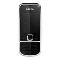
The phone is powered by a 3-pole battery (Li-Ion). The three poles of the battery are named VBAT, BSI and
GND, where the BSI line is used to recognize the battery capacity. This is done by means of an internal battery
pull down resistor.
Figure 9 Battery pin order
The battery temperature is estimated by measuring separate battery temperature NTC via the BTEMP line of
EM ASIC. This resistor is located on the main PWB, at a place where the phone temperature is closest to the
battery temperature.
RM-781
System Module
Page 5 – 6 COMPANY CONFIDENTIAL Issue 1
Copyright © 2011 Nokia. All rights reserved.