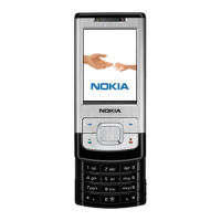
Type Description
GPIB control cable
Module jig MJ-136 set up
Figure 6 Module jig MJ-136 set up (PWB for RM-240 us used)
1 Remove the PWB, antenna IHF assembly, bottom keymat assembly and bottom flex from the phone.
2 Fit the PWB according to illustration above and connect the top flex connector.
3 Fit the antenna IHF assembly and lock it.
4 Close the supporting frame of the jig over the PWB.
5 Pass the bottom flex connector through the lid in the jig and connect it on the backside of the jig.
6 Fit the bottom flex to the jig by using 2 screws and place the bottom keymat on top.
7 Pass the top flex connector through the jig and connect it on the back side.
8 Put the phone upper part in place on the jig.
RM-240
Service Devices and Service Concepts
Issue 1 COMPANY CONFIDENTIAL Page 2 –21
Copyright © 2007 Nokia. All rights reserved.

 Loading...