WW Competence Transfer
CMO Operations & Logistics
Multimedia Creation & Support CONFIDENTIAL
21.11.2005
14
Service Manual 7360 RM-127 Copyright © 2005 NOKIA Corporation. All rights reserved.
Approved 1.0
MGR
Page
(26)
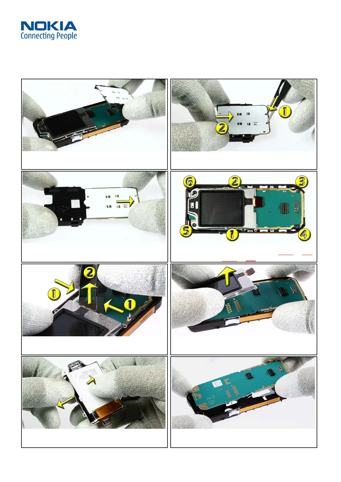
17. Remove the UI PWB Holder including the UI MODULE from
the Engine Module.
18. Hold the UI PWB HOLDER with your fingers. Press the snaps
down with the tweezers and hold it while moving the UI
MODULE to the right.
19. Now remove the UI MODULE from the UI PWB HOLDER. 20. Unscrew the six Torx Plus® size 6 screws in the order shown.
For Assembly use the reverse order. IMPORTANT: Torque for used
B-Cover Assy = 23Ncm. Torque for new B-Cover Assy = 28Ncm
21. . Use the SS-34 to open the connector of the LCD MODULE. 22. Separate the UI SHIELD ASSY including the LCD MODULE from
the ENGINE MODULE.
23. Slightly bend the UI SHIELD ASSY and press out the LCD
MODULE. Prevent deforming the UI SHIELD ASSY
24. .Remove the ENGINE MODULE from the B-COVER ASSY
 Loading...