WW Competence Transfer
CMO Operations & Logistics
Multimedia Creation & Support CONFIDENTIAL
21.11.2005
16
Service Manual 7360 RM-127 Copyright © 2005 NOKIA Corporation. All rights reserved.
Approved 1.0
MGR
Page
(26)
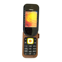
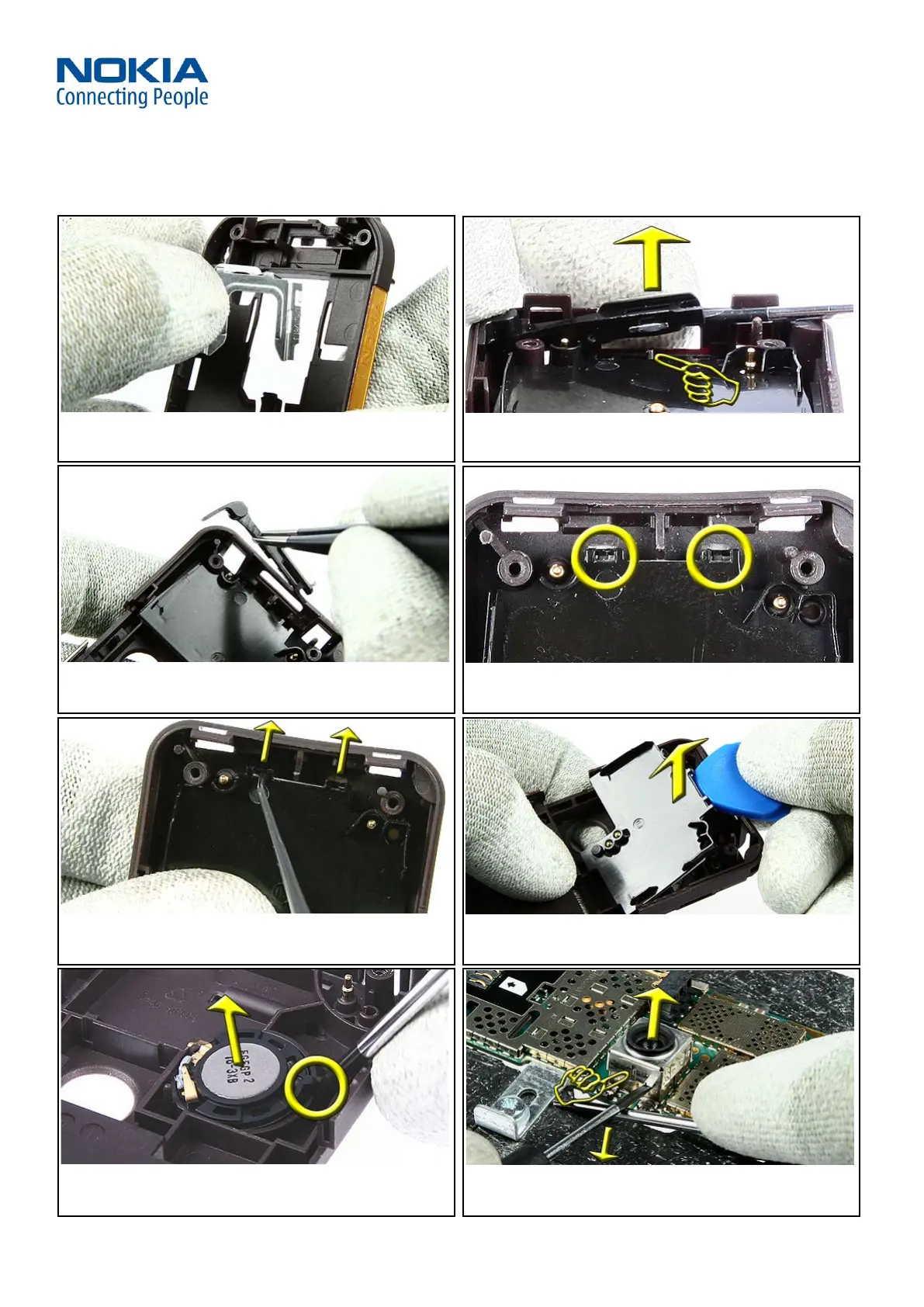
33. Remove the SIM-GRIP from the B-COVER ASSY. 34. Hold the POWER KEY depressed and use a slotted screwdriver
to lever it over the marked position (yellow finger).
35. Use tweezers to remove the POWER KEY ACTUATOR including
the POWER KEY. Both items can be disassembled if necessary.
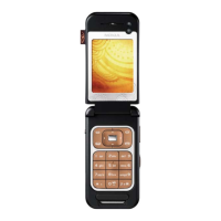
36. Note the two snaps of the IHF LID ASSY.
37. Use the dental tool to open both snaps. Be careful not to
damage the snaps. A click noise is audible if the snaps open.
38. Use the SRT-6 to remove the IHF LID ASSY.
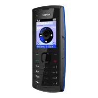
39. Use the dental tool to remove the adhered IHF SPEAKER. For
assembling not the guide pin. Use always a new IHF SPEAKER
ADHESIVE when assembling.
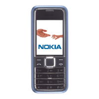
40. Place the ENGINE MODULE into the module jig. Use a
slotted screwdriver as a lever to open the CAMERA SHIELD. For
assembling note the guide pin.
 Loading...