Do you have a question about the Nokia DNT2Mi sp/mp and is the answer not in the manual?
Introduces the DNT2Mi Data Network Terminal and provides installation/use information.
Describes the DNT2Mi as a data access network terminal for customer premises.
Explains DNT2Mi usage for LAN, PABX, and point-to-point connections.
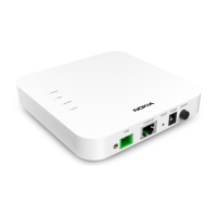
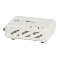
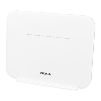
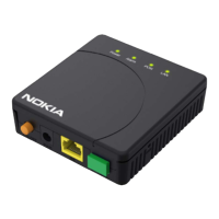
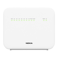
Introduces the mechanical construction and interfaces of the DNT2Mi.
Details the DNT2Mi front panel components: display, LEDs, keys, and connector.
Explains the function and state of front panel LEDs and keys.
Describes the local management interface and its connection for PC/software management.
Details the rear panel connectors and interfaces for different DNT2Mi units.
Briefly introduces DTE interface unit options and refers to a separate document for details.
Provides instructions for mechanical installation and connection of the DNT2Mi.
Outlines conditions for DNT2Mi to comply with EMC specifications.
Explains grounding requirements for AC and DC powered DNT2Mi versions.
Specifies recommended clearances for DNT2Mi installation for proper air circulation.
Provides a step-by-step guide for installing the DNT2Mi, including checks and connections.
Details the procedure for inserting DTE interface units into the DNT2Mi terminal.
Provides instructions for installing the DNT2Mi in a free-standing configuration.
Covers mechanical installation into a 19-inch rack or on a wall.
Provides detailed steps for wall mounting the DNT2Mi unit.
Details the steps to uninstall a wall-mounted DNT2Mi unit.
Explains how to install a modem shelf into a 19-inch rack or cabinet.
Guides on installing the DNT2Mi unit into an already installed modem shelf.
Details the procedure to uninstall the DNT2Mi unit from a modem shelf.
Specifies requirements for connecting the mains power supply to the DNT2Mi unit.
Provides troubleshooting tips for common issues like backlight, resets, and status LEDs.
Explains how to guide the power cable through the strain relief for secure connection.
Covers final steps to verify installation and adjust settings.
Guides on how to verify the DNT2Mi installation is correct after power-up.
Explains how to adjust the LCD contrast for optimal viewing angle.
Recommends actions like labeling units/cables and cleaning the site.
Describes checks needed before taking the DNT2Mi into use.
Explains the automatic self test performed when the unit is powered on.
Details items to check for DNT2Mi management via line, local, or port connection.
Explains how to know the network timing source before connecting DNT2Mi.
Lists line interface settings to check, including SHDSL mode and rate adaptive.
Notes that adapter unit types are recognized and can be configured.
Describes how DNT2Mi maps time slots from the line connection directly to a port.
Explains how DNT2Mi settings can be protected with a password and front panel key rights.
Recommends line quality and BER tests after settings are checked.
Lists default values that can be recalled from the Q1 menu path.
Explains settings considered factory settings that can be recalled.
Describes how to get general information and statistics, and deals with alarms/faults.
Explains how to get unit name, type, codes, and versions via menus.
Details the Fault display for error information, unit type, and fault status.
Explains that DNT2Mi tests can be controlled via front panel or Q1 menus.
Lists parameters for quality, line, and error counters viewed via menus.
Describes the front panel menus and how to navigate them using keys.
Illustrates the main menu structure and navigation flow for front panel menus.
Guides on how to configure unit parameters via the menu interface.
Details the configuration steps for Port 1, covering timing, DTE circuits, and loop control.
Explains how to perform settings on a line, including SHDSL mode and line rate.
Covers common settings like timing source, time slots, management speed, and panel keys.
Shows the front panel menus for applying default settings to ports, line, or all.
Describes how to initiate tests for ports, lines, and the equipment itself.
Details the front panel menus for performing TR, LL, DL, and RLTR tests on ports.
Explains the front panel menus for performing DL tests on the line.
Shows the front panel menus for initiating equipment self-tests.
Describes how to monitor ports, lines, and equipment information via menus.
Details front panel menus for monitoring port signal quality and statistics.
Illustrates front panel menus for monitoring line measurements and signal quality.
Shows front panel menus for monitoring various line and port alarms.
Details front panel menus for viewing equipment information like SW and HW versions.
Shows front panel menus for accessing self test results and unit errors.
Introduces the Q1 menu structure and available options for DNT2Mi management.
Lists the 11 menus available in the Q1 main menu level for DNT2Mi.
Explains the DNT controls menu for activating tests and checking test status.
Describes the DNT settings menu for configuring various parameters.
Shows an example of the first display in the DNT Settings menu, showing current settings.
Explains Q1-specific configurable options like speed, address, and management path.
Allows selection of a timing source for the DNT2Mi from Internal, Line, Port1, or Transparent.
Covers line settings including SHDSL mode, wire mode, and line rate.
Allows selection and configuration of settings for each of the three ports.
Describes viewing and configuring the mapping of time slots between line and ports.
Explains how to set default configurations for ports, line, or all settings.
Details loading factory settings to restore default structures and configurations.
Provides information on port, line, and system statistics.
Allows setting a new password and restricting user rights for configuration/testing.
Lists technical specifications for the DNT2Mi terminal.
Provides dimensions and weight for multiport and single-port DNT2Mi units.
Details power consumption, voltage, frequency, and interruption tolerance.
Lists supported interchangeable DTE interface types and line interface rates.
Explains how to identify the unit using the sticker codes for manufacturing and product.
Covers environmental and mechanical requirements based on ETSI specifications.
Details ETSI specifications for transportation, storage, and operation.
States compliance with EMC specifications.
Lists safety and protection requirements following electrical and surge protection standards.
Provides charts to mark down results of the commissioning procedure.
| Brand | Nokia |
|---|---|
| Model | DNT2Mi sp/mp |
| Category | Touch terminals |
| Language | English |