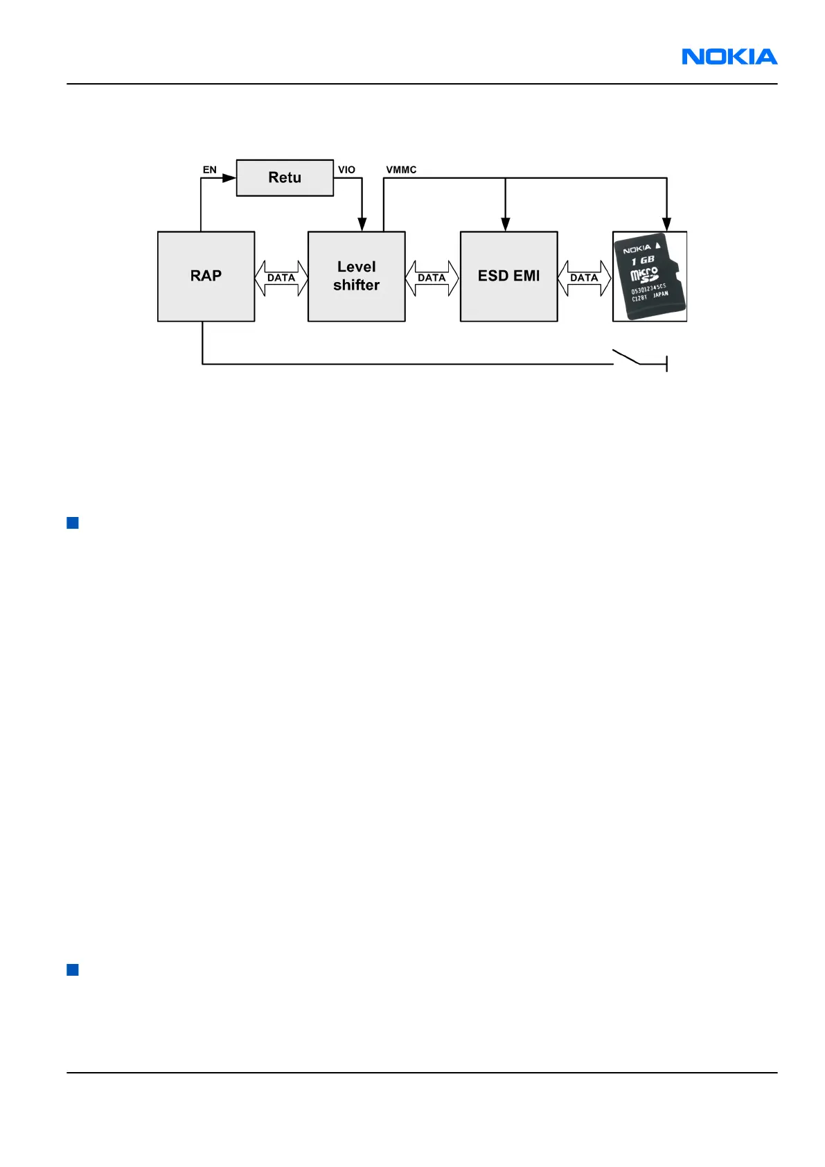
µSD card interface
The µSD card is connected to the engine by an external level shifter and ESD protection filter. Supplied
voltages:
• VMMC: 2.85 V (from level shifter)
• VIO: 1.8 V (from Retu)
The card removal is detected by a push detect switch.
User interface
Display
The display unit comprises a parallel interface.
Keyboard
All keys are placed on the main PWB.
• Numeric keys
• Navigation key, Soft keys, Start, and End
• Power switch
• Volume up and down switch
Display and keypad backlight
There are two sets of LEDs illuminating the display and the keypads:
• Display LEDs, 4pcs
• Main keypad on PWB, 4 pcs, white colour
All sets share the same driver. None of the keypads can be illuminated without the LCD backlight being turned
on.
Reminder lights
Two additional blue LEDs serve as reminder lights for missed calls/text messages.
Audio concept
Audio concept
The functional core of the audio hardware is built around two ASICs; RAP engine and Retu.
Retu provides an interface for the trancducers and the AV connector.
RM-217; RM-222
System module Nokia Customer Care
Issue 1 COMPANY CONFIDENTIAL Page 8 –13
Copyright © 2007 Nokia. All rights reserved.