EasyManua.ls Logo

nologo START-S4XL User Manual

Default Icon
14 pages
To Next Page IconTo Next Page
Page #1 background imageLoading...
Page #1 background image
START-S4XL
START-S4XL_290113_VXX13_GB www.ebtechnology.it www.nologo.info
FUSE 5A
FUSE 200mA
1 2 3 4 5 6 7 8 9 10
1 2 3 4 5 6 7 8 9 10 11 12 13 14 15 16 17 18 19 20 21 22 23 24 25
1 2 3 4 5 6 7 8 9 10
230Vac
20
40
60
80
100
0
2
6
8
MAX
4
10
MIN
2
6
8
OFF
4
10
FORCE
PHASE
DISPLACEMENT
SLOW
DOWN
TIMES
CODE
DIP A DIP B
Reset of the control board:
Press button “CODICI” and “TIMES”
for 10 seconds
OPEN
CLOSE
CODES
230 Vac Phase
230 Vac Lamp
230 Vac Lamp
Motor 1 COMMON
Motor 1 OPEN
Motor 1 CLOSE
Motor 2 COMMON
Motor 2 OPEN
Motor 2 CLOSE
Open. Limit Switch Mot. 2
Clos. Limit Switch Mot.1
Closing photocell
Start Button
24Vac
24 Vac/12Vac elect. lock
12Vac electrical lock
STOP
PEDONALE Botton
Photocell always working
COMMON contacts -
Antenna +
Earth -wire
Light / Lamp.
Light / Lamp.
Fototest 24Vac
12Vac
24Vdc +
COM 24Vdc -
26 27 28 29 30 31
1 2 3 4 5 6 7 8
DIP C
Remove of the inputs
• Single phase for 230 Vac 2 motors
• Universal control unit for 1 or 2 motors swing
• 4 limit switches
• Separate slow down
Clos. Limit Switch Mot. 2
Open. Limit Switch Mot.1
433,92 Mhz
Radio-decode
Radio-receiver
Question and Answer IconNeed help?

Do you have a question about the nologo START-S4XL and is the answer not in the manual?

nologo START-S4XL Specifications

General IconGeneral
Brandnologo
ModelSTART-S4XL
CategoryReceiver
LanguageEnglish

Summary

Foreword

Safety and Environmental Measures

Environmental Protection Measures

Guidelines for proper disposal of electronic equipment to protect the environment.

Introduction to START-S4XL

Product Description and Application

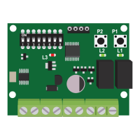
Overview of the START-S4XL unit's features, capabilities, and intended use.

Installation Overview

Preliminary checks and general guidelines for installing the control unit.

Electrical Wire Specifications

Cable Types and Standards

Details required cable types, sections, and adherence to IEC standards for installations.

Installation Guidance and Notes

Installation Procedures and Safety

Guidance on installation, risk analysis, photocell synchronization, and connection safety.

Terminal Connection Details

Terminal Mapping and Functions

Detailed list of all terminal connections and their corresponding functions on the control board.

Connections and Setting Up Parameters

Operational Parameters

Explanation of key parameters like TIME, CODES, FORCE, PHASE-DISP., SLOW DOWN.

Status Indicator LEDs

Description of LED lights indicating the automation's status.

Functions and Adjustments

DIP A Switch Functions

Details the functions enabled by the micro-switches on DIP A for various operations.

DIP B Setup and Configuration

DIP B Operational Modes and Time Learning

Explains the settings for DIP B, including operational modes and time learning configurations.

DIP C Input Enable/Disable

DIP C Input Management

How to enable or exclude specific inputs like limit switches and photocells using DIP C.

Remote Control Management

Remote Control Memory Operations

Procedures for clearing all learned remote codes and for programming new remote controls.

Time Learning: Normal Way

Normal Way Procedure

Standard method for teaching gate working times for uniform motors.

Time Learning: Advanced Systems

Advanced System Procedure

Advanced method for setting gate times with precise slowdown control.

Partial Opening Procedure

Procedure for setting times specifically for pedestrian or partial gate opening.

Time Learning: Fastest Way

Fastest Way Procedure

Quickest method for learning the pause time for gate operation.

System Reset and Testing

Control Board Memory Reset

How to reset the control board to its original factory settings.

Test Function Operation

Instructions for using the TEST function to verify device connections and operation.

Related product manuals