IIC Output
Copyright © Nooploop LTd 2023. All Rights Reserved.
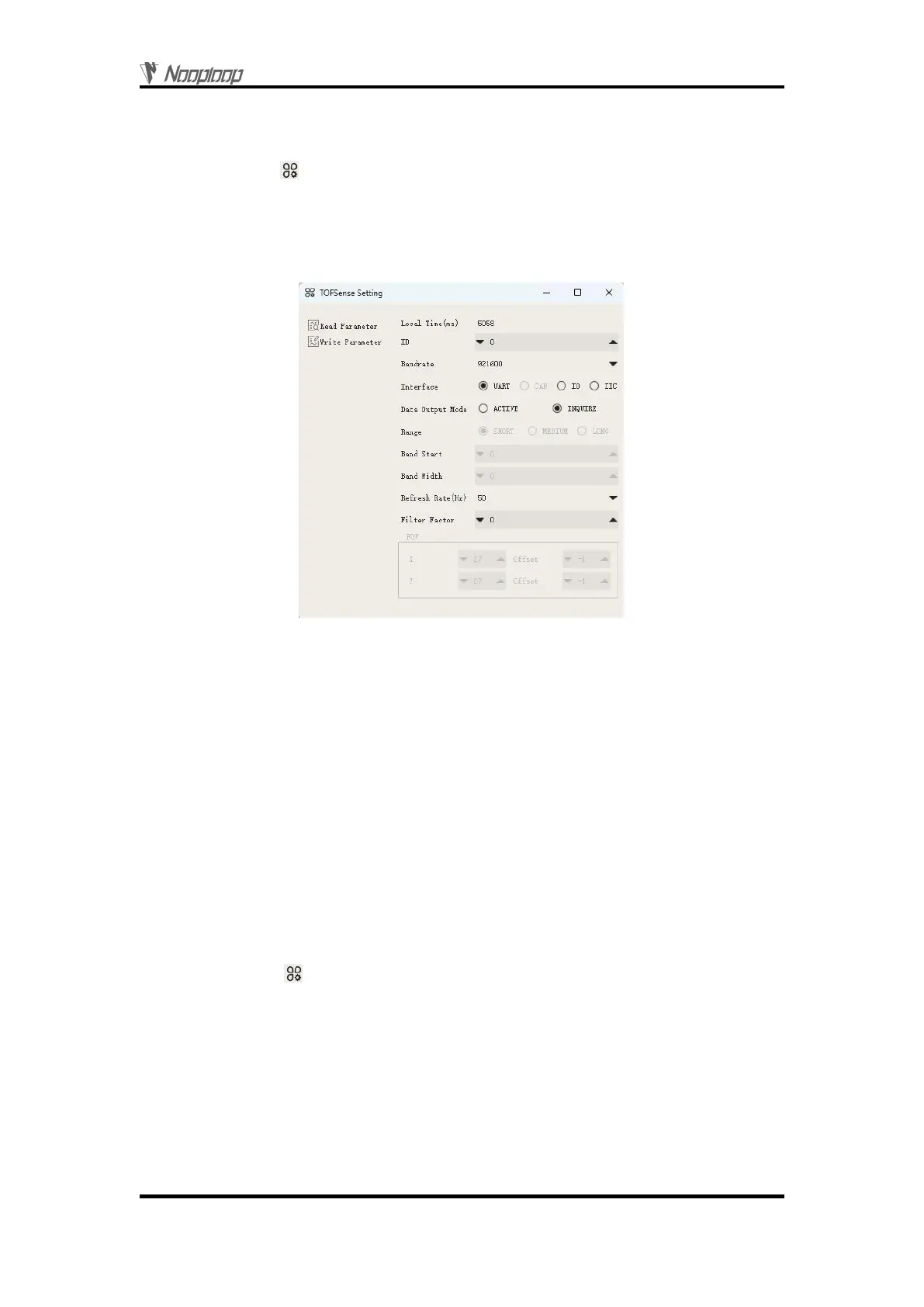
To connect TOFSense-F series products to the NAssistant software via a USB to TTL module
(referring to the data manual for wiring and power voltage), after successful identification, click to
enter the setting page . The configuration diagram for UART query output mode is shown in Figure
2. After configuring the parameters, you need to click the 'Write Parameters' button to save the
parameters. Once the parameters are written successfully, you can read the parameters once to confirm
if they have been successfully saved. (After changing the baud rate parameter of the module, you need
to unplug and replug the USB to TTL module for the module to be automatically recognized.)
Figure 2: Configuration diagram for UART query output mode
3
IIC Output
3.1 IIC Communication
In IIC communication mode, the controller can send a read frame to the specified slave address of
the module to be queried according to the IIC communication timing to obtain distance and other
related information of the module. In addition, various parameters such as the output mode of the
module can also be changed through IIC communication. The format of the read and write frames
follows the NLink_TOFSense_IIC_Frame0 protocol.
When the module is in UART mode (note that NAssistant cannot recognize modules in IIC mode),
TOFSense-F series products can be connected to the NAssistant software via a USB to TTL module
(referring to the data manual for wiring and power voltage). After successful identification, click to
enter the setting page . The configuration diagram for IIC output mode is shown in Figure 3. The
IIC slave address of the module (7-bit slave address is 0x08 + module ID, and the ID setting range is 0
to 111) can be changed by setting the module ID. After configuring the parameters, you need to click
the 'Write Parameters' button to save the parameters.
Note: After switching to IIC mode, please refer to the FAQ section for a way to switch back to
UART mode.