42
5.
To return to the operating screen, press and hold SETUP for two
seconds.
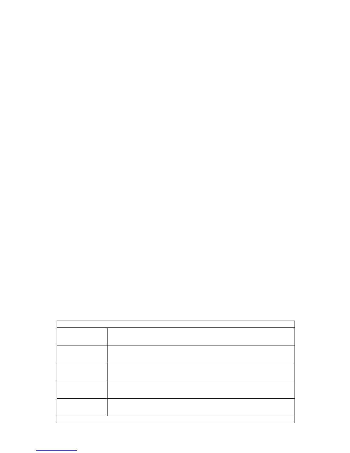
6.6.1.3 Special Features of the Main Roll (MR) Sensor
The main roll sensor provides the two height readings necessary for control
of the main roll boom section. The two readings necessary are the spring
height "Sht", and the cylinder height "Cht". Normally all height readings
shown on the UC4 panel are displayed in inches, however, these two
readings are displayed in millimeter resolution. You can see these height
readings in their appropriate submenus (see Section 5.4.3).
The spring and cylinder are displayed as a change in height from boom’s
centered position. In other words, with the boom level and centered the
spring and cylinder should read zero. You can calibrate these readings in
the same manner as described in the previous section. However, it is
imperative that the boom is centered and level when calibrating.
In addition to providing these two readings, it may also be possible for the
main roll sensor to provide the height reading necessary for controlling the
main up/down boom section. This will be configured for you automatically
during the "Install ?" or "Initial Power Up" sequences. If this is the case,
the MAIN boom’s sensor serial number will be labeled as "PROXY". This
indicates that the MR sensor is providing all three height readings.
6.6.2 Setting Up Hydraulic Valves
There are two key settings for each valve direction (for example, the left up
direction). These settings are valve deadzone - abbreviated DZ, and valve
gain - abbreviated KP. The deadzone setting represents the size of electrical
signal required at the solenoid valve to cause a boom speed of one inch per
second. The gain setting is inversely related to the maximum speed of the
boom. That is, the faster the boom the lower the gain setting.
The left channel is described below. For the other channels the basic
structure and behavior is the same..
Navigating past the end of the menu will return the panel to the Setup…More Menu
Left On
Left OnLeft On
Left On
Informs you that the left valve channel is ON. To change the status
to OFF use the +/- switch.
↑
↑↑
↑DZ
DZDZ
DZ-
--
- 100
100 100
100
Informs you that the left up deadzone setting is 100. To adjust the
reading use the +/- switch.
↑
↑↑
↑KP
KPKP
KP-
--
- 53
53 53
53
Informs you that the left up gain setting is 53. To adjust the
reading use the +/- switch.
↓
↓↓
↓DZ
DZDZ
DZ-
--
- 100
100 100
100
Informs you that the left down deadzone setting is 100. To adjust
the reading use the +/- switch.
↓
↓↓
↓KP
KPKP
KP-
--
- 42
42 42
42
Informs you that the left down gain setting is 42. To adjust the
reading use the +/- switch.
Navigating past the end of the menu will return the panel to the Setup…More Menu