2
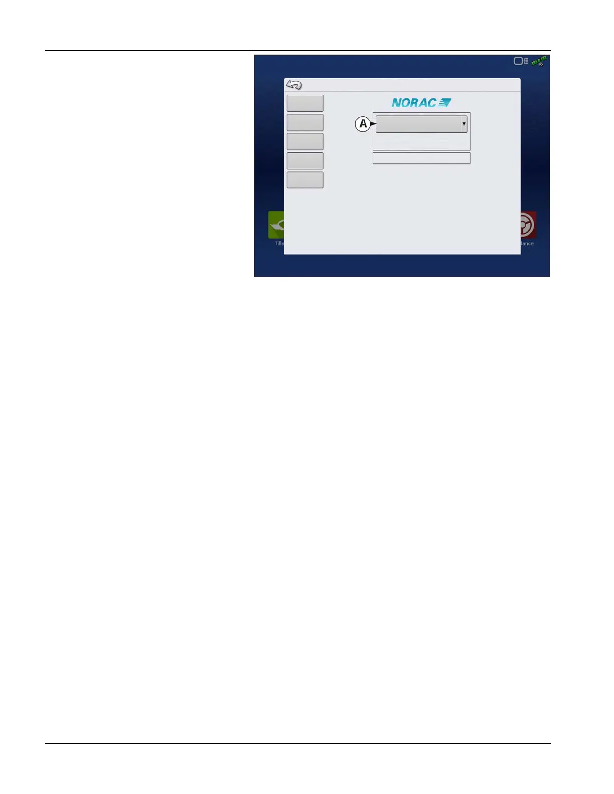
A. Norac Devices drop-down menu—The
drop down menu shows the devices
communicating on the NORAC UC5 CAN
Bus along with the serial number of each
device. The Firmware Version and
Hardware Revisions of your NORAC UC5
devices are shown underneath.
• Automatic Setup—Automatic Setup
walks through a series of steps that
configures the NORAC UC5 electronics to
the sprayer hydraulic functions. You must
perform an Automatic Setup routine after
the NORAC UC5 system is installed. The
following items are configured during an
Automatic Setup routine:
• Sprayer Make and Model
• Input module wiring and
configuration
• Number of sensors and location
• Sensor zero point
• Valve deadzone and gain values.
÷
NOTE!: For detailed Automatic Setup information, see the NORAC UC5 manual.
• Sensors and Valve Drivers—Opens the Sensor and Valve Driver Settings screen (for more detail see the next page).
• Boom Control Module—Turn motion detection on/off, choose source as GPS or AUX.
• Advanced Settings—For use by a technician.
• Retune—From time to time it may be necessary to recalibrate (Retune) the UC5 electronics to your sprayer’s
hydraulics. Examples of such times are:
• When a hydraulic solenoid valve is changed.
• When the hydraulic pump is changed or adjusted.
• When the normal working temperature of the hydraulic oil has shifted significantly from when the system was
previously calibrated.
If you are running a pull type sprayer and use different tractors to operate the sprayer, you should run the Retune procedure
each time the tractor is changed. If you have a flow control for the boom hydraulics, set it prior to tuning. If you change the
flow setting by more than 20 percent, you should Retune.
Norac UC5
Automatic
Setup
Firmware Version
Hardware Version
Sprayer Configuration: Sprayer Model
Unknown
Unknown
Controller #300
Sensors and
Valve Drivers
Boom Control
Module
Advanced
Settings
Retune