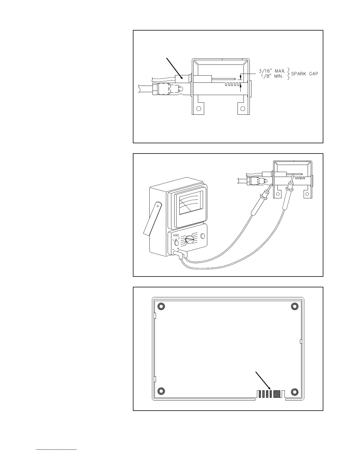
25. Check that the alignment of
the electrodes is correct as
shown in Figure 11.48
26. Check the Ignition electrode
shown in Figure 11.49 for a
short to ground.
A. Turn the Mode Selector to
OFF.
B. Set the volt-ohm-meter to
the Rx 10K scale.
C. Disconnect the wire to the
electrode.
D. Check the continuity to
ground as shown in Figure
11.49.
E. Any reading indicates a de-
fective electrode and it
must be replaced.
27. Reconnect the electrode and
set the Mode Selector back
to GAS.
28. Check that the Burner and Ori-
fice shown in Figure 11.49 are
not obstructed.
29. Check for corrosion on the
pins of the Ignition Module
as shown in Figure 11.50. If
corrosion exists clean with
an eraser.
30. If the flame will not ignite and
remain lit, replace the Ignition
Module.
Figure 11.49 Electrode Grounding Check
Corrosion Build Up
Figure 11.50 Edge Connector Visual Inspection
Ignition Electrode
Figure 11.48 Proper Electrode Gap
40