Owner’s Manual 22
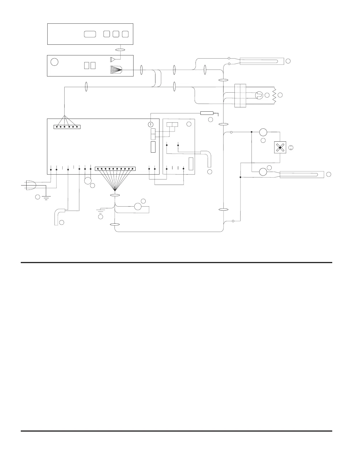
Ice Maker Wiring Pictorial and Diagram
(N64XIM, N64XIMXX, N84XIM, and N84XIMXX models)
The parts of the ice maker wiring pictorial and diagram are (See Art01500):
120V AC Hot .........................................................................................................................................................................................109
PC Board ................................................................................................................................................................................................49
Ground screw ....................................................................................................................................................................................... 111
Hot / smooth ......................................................................................................................................................................................... 112
Neutral / Ribbed.................................................................................................................................................................................... 113
Solenoid Water Valve .............................................................................................................................................................................44
Thermal Fuse ....................................................................................................................................................................................... 114
Ice maker .............................................................................................................................................................................................. 115
Mold Heater .......................................................................................................................................................................................... 116
Thermostat .............................................................................................................................................................................................96
Shut Off Switch .....................................................................................................................................................................................117
Fill Switch ............................................................................................................................................................................................. 118
Holding Switch ...................................................................................................................................................................................... 119
Motor ....................................................................................................................................................................................................120
120V AC Neutral ................................................................................................................................................................................... 110
Art01876
5
L1
L2
P1
5
OVERLAY/REVÊTRMENT
DISPLAY BOARD/
CARTE D’AFFICHAGE
POWER BOARD/ PANNEAU D’ALIMENTATION
+12VDC/VCD
4
P2
T1
5 AMP
AC_HT_HI_2
LIMIT_IN
LIMIT_OUT
AC_HT_LO
AC_HT_HI
AC_HT_LO_2
GND
12VDC
L
K
A
10
L
7
-12VDC/VCD
B
C
6 1
10
1
GND
GND
12V
12V
HTR_GND
DC_HTR
M
30 AMP
D
E
3
2
5
1
1
1
H
G
I
2
3
J
6
1
8 AMP
F2
F1
*
F1
*
*
F
P