Owner’s Manual 23
Art01500
109
110
111
114
115
N
G
L
44
GRN / VERT
BRN / BRUN
WHT / BLANC
BLK / NOIR
NEUTRAL (RIBBED) /
NEUTRE (À NERVURES)
WHT / BLANC
HOT(SMOOTH)/
CHAUD (PLAT)
GRN / VERT
109
114
116
120
119
96
118
44
117
110
111
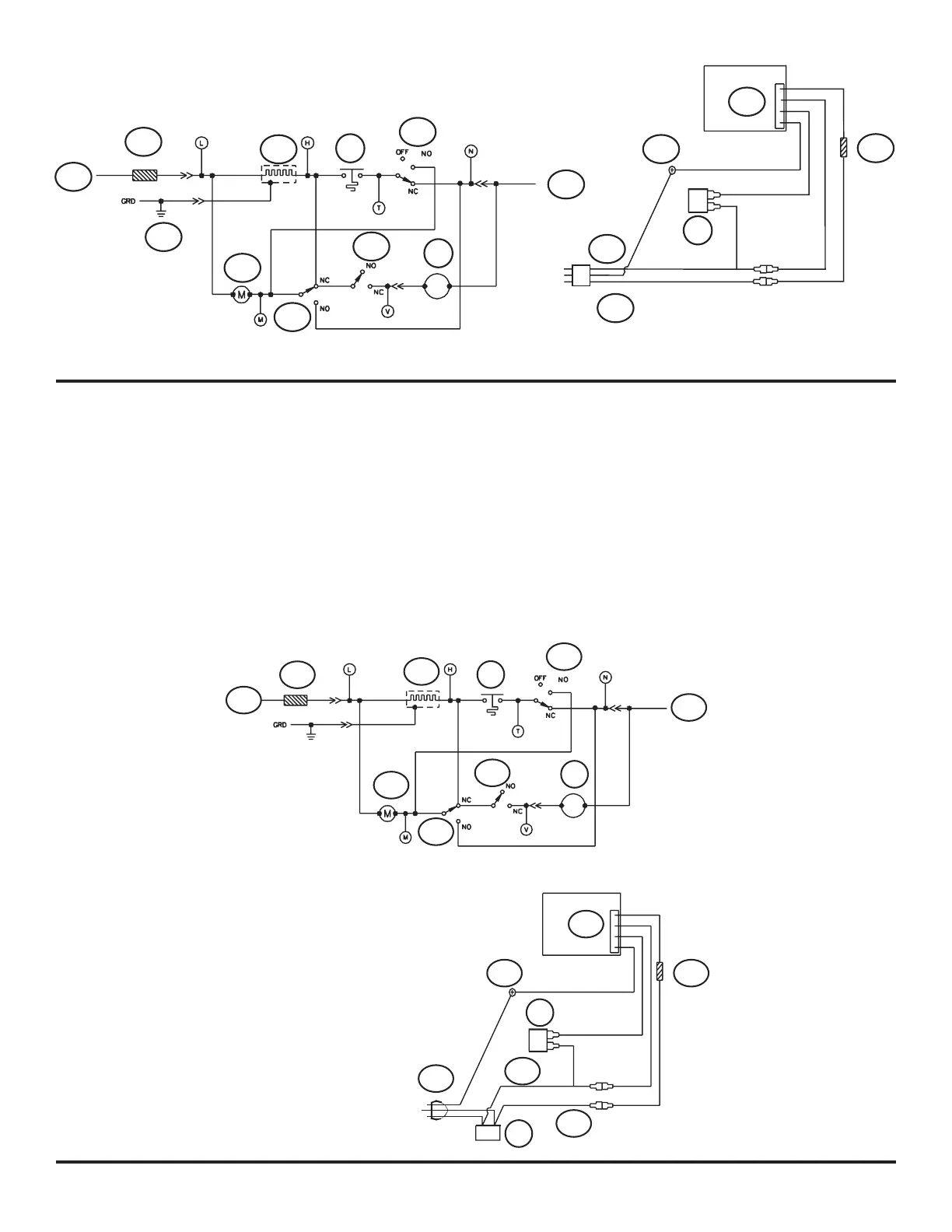
The parts of the ice maker wiring pictorial and diagram are (See Art01016):
120V AC Hot .........................................................................................................................................................................................109
120 VAC Neutral ................................................................................................................................................................................... 110
Ground screw ..................................................................................................................................................................................... 1113
Thermal Fuse ....................................................................................................................................................................................... 114
Solenoid Water Valve .............................................................................................................................................................................44
Ice Maker .............................................................................................................................................................................................. 115
Mold Heater .......................................................................................................................................................................................... 116
Thermostat .............................................................................................................................................................................................96
Shut Off Switch .....................................................................................................................................................................................117
Fill Switch ............................................................................................................................................................................................. 118
Holding Switch ...................................................................................................................................................................................... 119
Motor ....................................................................................................................................................................................................120
Ice Maker Wiring Pictorial and Diagram (model N843IM)
109
114
116
120
119
96
118
44
117
110
Art01016
109
49
111
112
113
44
114
115
L
N