NORDAC Control and Parameter Boxes
12 Subject to technical alterations BU 0040 GB-1611
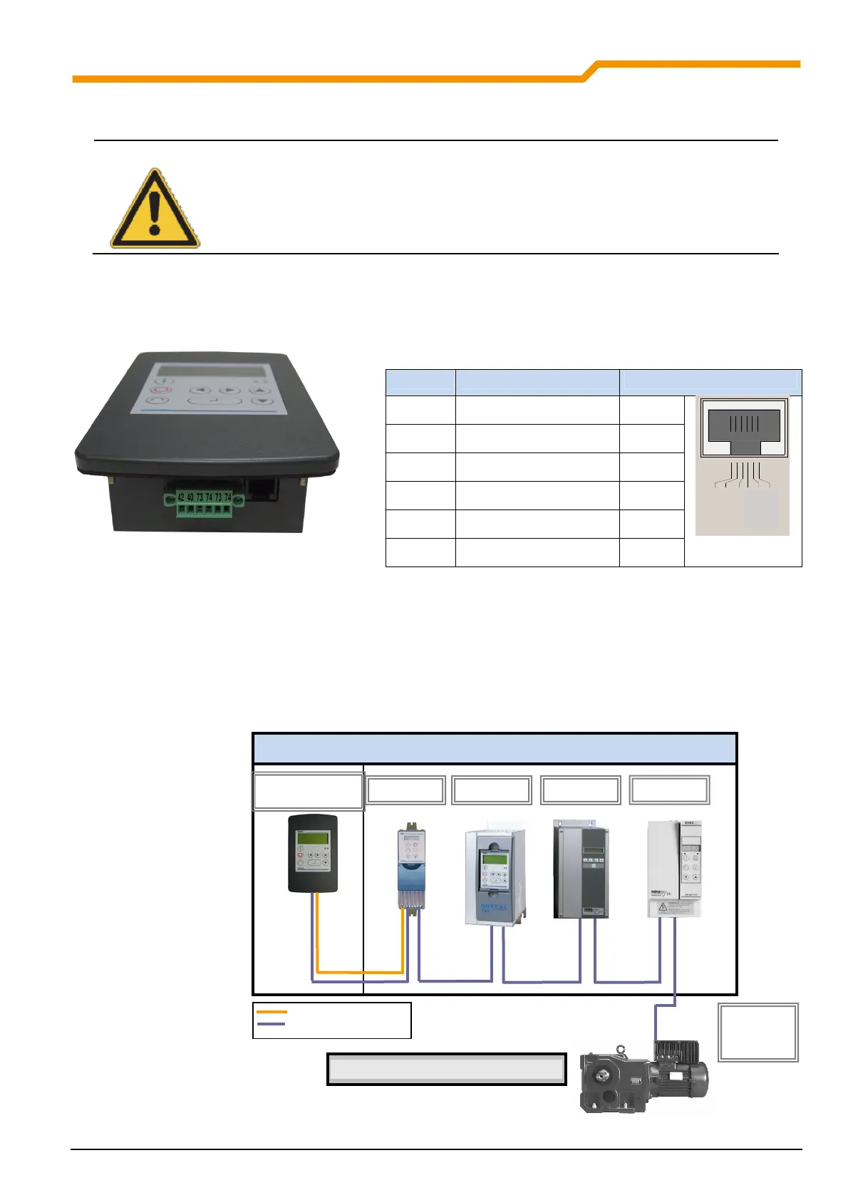
2.1.2.2 Electrical connection
WARNING
Installation must be carried out by qualified personnel only, paying particular attention to safety
and warning instructions.
Installation or removal of modules or electrical connections must only be carried out when no
voltage is present. For detailed information, please refer to the relevant frequency inverter
manual.
The SK PAR-2E ParameterBox is connected via the 6-pin screw connector or the RJ12 plug. The power supply can
either be from the inverter or a separate supply unit. The permissible voltage range is +4.5V to +30V DC.
Number Description RJ 12
42 + 4.5V… 30V / 1.3W 6
40 GND 3
73 P+ (A) (RS485 +) 1
74 P- (B) (RS485 -) 2
- - 4
- - 5
RS485_A
RS48 5_B
GND
TXD
RXD
+5V
+5V - 30V
1 2 3 4 5 6
A termination resistor (220Ω) for the RS485 bus system is integrated into the module. Therefore the ParameterBox
should only be connected as the first or last participant.
The terminals are designed for 0.14 mm² - 1.5 mm
2
. A flexible cable with a cross section of 4 x 0,75mm
2
is
recommended.
The maximum possible connection cross section is 1.5mm
2
. With the use of certain wire end sleeves, the possible
cross-section may be reduced.
Schaltschrank
Gear unit motor with FI in field
SK PAR-2E
Part No. 278910110
SK 5xxE SK 700E vector CT
SK 2xxE
SK 300E
SK 750E
vector mc
Power supply
Data cable
 Loading...