Hardware description
Note: If a current-measurement resistor (IBAT) is mounted on R1 always make sure the P1 jumper
is disconnected.
4.7.2 NTC jumper
If using a battery without an NTC thermistor connect a jumper between NTC (pin 2) and 10 kΩ (pin 3) on
pin header P3, to use the integrated 10 kΩ resistor R9.
For a custom resistor there is an empty resistor footprint R10 available on P3 (pin 1). To use R10 connect a
jumper between RES (pin 1) and NTC (pin 2) on pin header P3.
The NTC schematic is shown in Figure 15: VBAT and NTC jumper schematic on page 21.
Pin Pin name Function
1 RES Resistor R10 to GND (unmounted)
2 NTC PMIC NTC input
3 10 kΩ Resistor R9 to GND
Table 8: NTC jumper header
4.7.3 Buck startup configuration
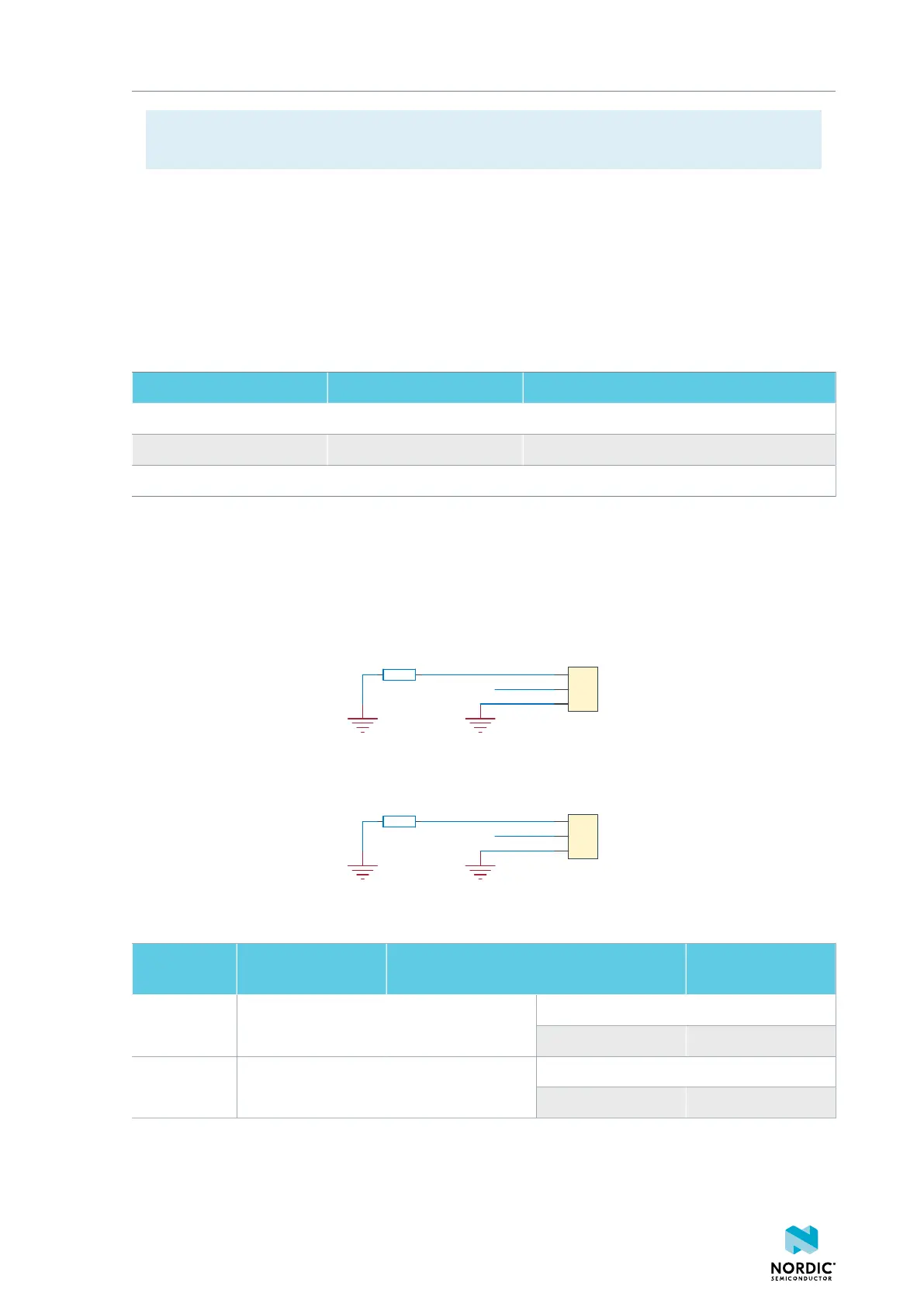
The nPM1300 PMIC requires a startup VSET condition for the BUCK regulators.
Use jumpers on P13 and P14 to connect VSET1 and VSET2 to the fixed resistors RSET1 and RSET2, or
to GND.
R3
47k 1
2
3
P13
Pin List 1x3
1
2
3
P14
Pin List 1x3
VSET2
R4
150k
RSET2_3V0
VSET1
RSET1_1V8
VSET1_OFF
VSET1_OFF
RSET1
RSET2
Figure 16: VSET schematic drawing
Configuration Pin header Jumper connection Buck output voltage
(VOUT)
RSET1 1.8 VBUCK1 P13 VSET1
GND 0 V (OFF)
RSET2 3.0 V
BUCK2 P14
VSET2
GND 0 V (OFF)
Table 9: Buck startup configuration
4490_387
22


 To Next Page