6
Use the nPM1300 EK with an
nRF5340 DK
The nPM1300 EK can power the nRF5340 System on Chip (SoC) as a host device on the nRF5340 DK.
Note: The EK only powers the nRF5340 SoC on the DK. To access the nRF5340 DK features such as
flashing and debugging, the IMCU on the DK must be externally powered.
To connect and configure the EK with the nRF5340 DK:
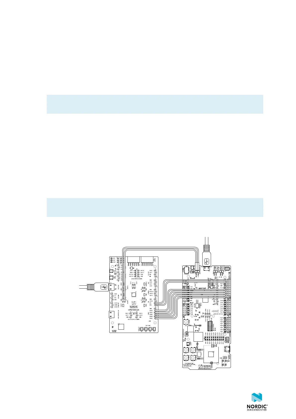
1. Connect the nPM1300 EK to the nRF5340 DK according to the connection diagram.
2. On the DK, make sure the VEXT→nRF switch SW10 is in the ON position. This connects the external
supply to VDD (in this case, VOUT2 on the PMIC).
3. On the DK, make sure the nRF POWER SOURCE switch SW9 is in the VDD position. This ensures that
only the nRF5340 circuitry is powered from VDD.
4. To flash and debug the nRF5340, connect a USB cable to the USB port J2 on the DK. This only powers
the IMCU used for flashing and debugging.
5. On the EK, disconnect the USB-C cable from J4 to put the EK in standalone mode. This disables the
nPM Controller.
6. Power the EK by connecting a desired power input source: VBUS, VBAT, or both.
Note: Both the nRF5340 host device and the PMIC have the same I/O reference level (VOUT2),
therefore VDDIO is redundant and not connected between the EK and the DK.
The following figure and table show the connections between the EK and the nRF5340 DK. A similar setup
might apply to the DKs of the nRF52-series or the nRF9160 DK (not covered in this user guide).
Figure 23: Connecting nPM1300 EK with nRF5340 DK
4490_387
35



 To Next Page