Disassembly and Repair 7-21
~ ~~~
3. Repah of applicator
(electrical)
Circuit board replacement
7
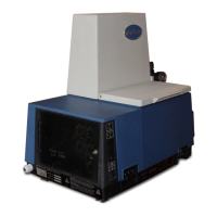
Figure 7.5 1 - Disconnecting Circuit Board
Connector J7.
1 Jumper (single-phase operation only)
1. Turn the main electrical switch OFF at the applicator and disconnect
input line voltage from the applicator.
+
43
WARNING: Shock hazard. Disconnect the applicator from
.
input electrical line voltage. Failure to disconnect line voltage
from the applicator may result in a serious electrical shock.
2. Remove the electrical cabinet cover by unscrewing the captive
screws on top of the cabinet.
3. Disconnect the white circuit board plug from its connector (labelled
J6 on the board) in the lower right corner of the circuit board.
4. Disconnect circuit board plug J7 from its receptacle on the circuit
board (see Figure 7.51).
5. Disconnect the white circuit board plugs from their connectors along
the top of the circuit board. There are two of these plugs on a Model
2302 Applicator, four on a Model 2304, and five on a Model 2305.
6. Using a long screwdriver, remove the two screws which secure the
frame for the circuit board and control panel door to the base of the
unit.
7. Rotate the top of the frame away from the unit and down towards the
floor. Now the whole frame assembly may be removed from the base.
8. Remove the six screws which secure the circuit board to the frame.
9. Secure the new circuit board to the frame with the six screws
removed in step 8.
10. Connect circuit board plug J7 to its receptacle on the circuit board.
11. Holding the frame so that its top is tilted away from applicator, match
the slots in the bottom of the frame with the slots in the base of the
unit. When the keyed slots interlock, rotate the top of the frame up
and towards the unit until it is standing upright.
12. Secure the frame to the base of the unit with the two large screws.
13. Connect the hose electrical plugs to their connectors along the top of
the circuit board. Connect the plug labeled 1 to the connector
labeled Jl on the circuit board, plug No. 2 to connector J2, and so
forth until all plugs are connected.
14. Replace the electrical cabinet enclosure and secure it with the
captive screw on top of the cabinet.
15. Reconnect input electrical line voltage to the applicator and resume
operation.
@ No&on Corporation 1994
All Rights Reserved
P/N 106 701A
41-23OOSP -Issued 1194
 Loading...