16
ELECTRICAL SYSTEM
INSTALLATION
!
WARNING:
To avoid the risk of electrical shock,
personal injury or death, disconnect
all electrical power to the unit before
performing any maintenance or
service. The unit may have more than
one electrical power supply.
Codes, Specifications, and
Requirements
The wiring, installation, and electrical hookup of
this furnace must comply with the National
Electrical Code (or the Canadian Electrical Code)
and all regulations of local authorities having
jurisdiction. See Table 6 for minimum circuit
ampacity, maximum over-current protection, and
recommended wire size. See the unit wiring
diagram for other wiring details.
Supply-circuit requirements are as follows:
• -010 model is factory-wired for single-branch
supply circuit only.
• -012 models are factory-wired for single-
branch supply circuit (single-circuit kit in-
stalled). Dual-branch circuit can be used by
removing factory-installed single-circuit kit
(see Figures 18 and 19).
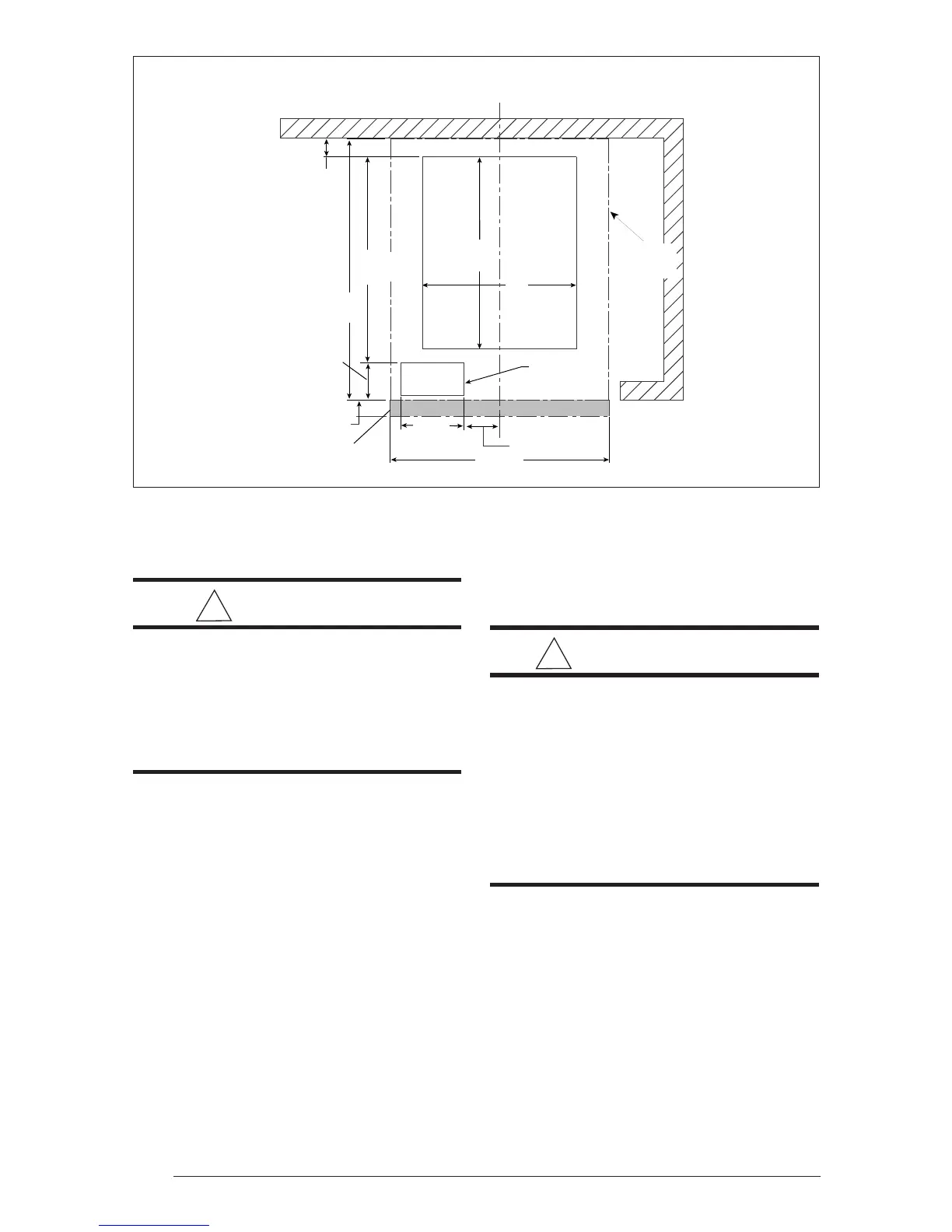
1 3/4" MIN
(45 mm)
23 3/4"
(604 mm)
3/4"
(20 mm)
20"
(508 mm)
17 1/2"
(445 mm)
14"
(356 mm)
5 3/4"
(147 mm)
3 1/8"
(80 mm)
3"
(73 mm)
Furnace
Outer Door
For Optional
A/C Or H/P
REAR WALL OF ENCLOSURE
CENTER LINE
Furnace
Outline
18 5/8"
(474 mm)
Figure 17. Upflow Floor Cutout Locations (nominal dimensions)
• -015, -017, -020 and -023 models are
factory-wired for dual-branch supply circuit.
Single-branch circuit can be used by
installing optional single-circuit kit .
!
IMPORTANT:
Note: Circuit breakers installed within
this unit are for short-circuit
protection of the internal wiring and
to serve as a disconnect. Circuit
breakers installed within this unit DO
NOT provide over-current protection
of the supply wiring and therefore may
be sized larger than the branch circuit
protection.
Connecting Supply Service Wires
1. Remove right-hand control panel (when
viewing in downflow position).
2. Locate power supply hole plugs in side of
unit and in bottom of unit. Remove
appropriate plug(s) or knockout opening
applicable to recommended wire size(s).
3. Install listed cable connector(s) in
opening(s). If metal-sheathed conduit is
used for incoming power line(s), provide an
approved metal clamp on conduit and
secure it in entrance knockout.
 Loading...