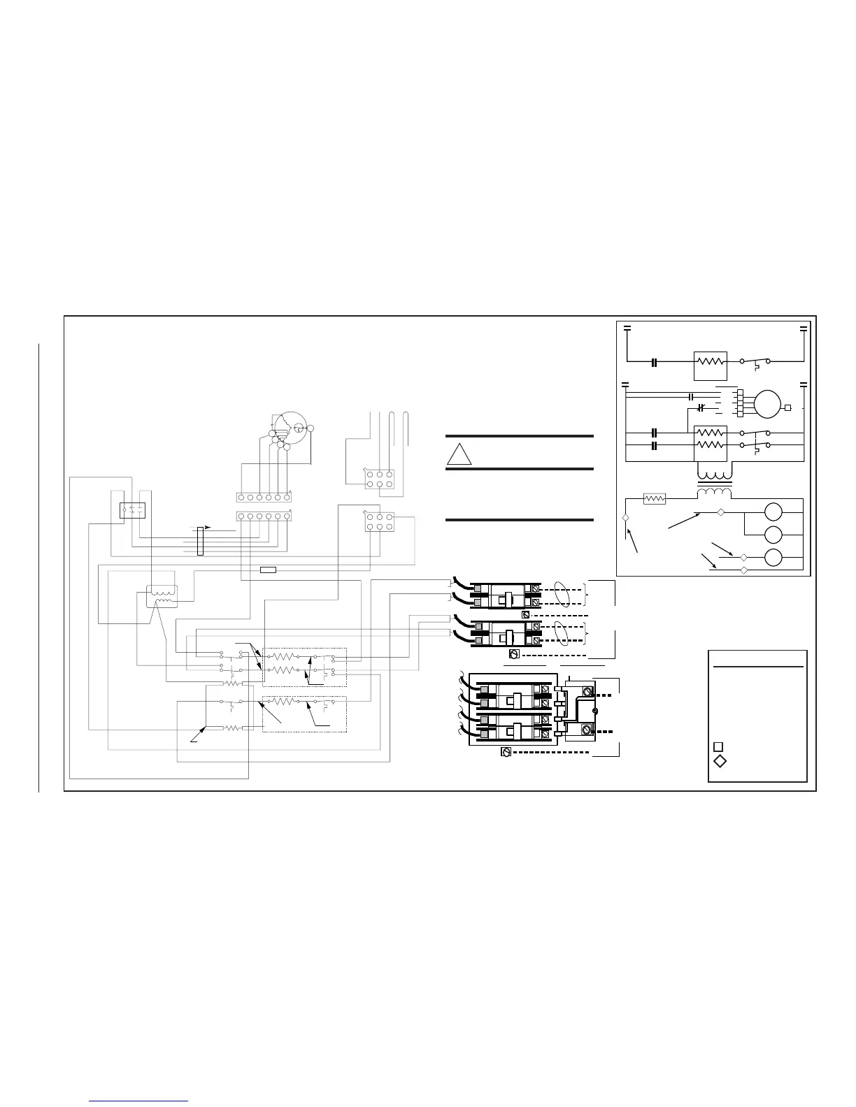
WARNING:
Switch circuit breakers to
the OFF position beore
servicing the furnace.
TRANSFORMER
240V
24V
SEQUENCER
LIMITS
TOP ELEMENT, 10.0/10.8 KW
BLACK
RED
ELEMENTS
BOTTOM ELEMENT, 5.0/5.4 KW
H
MH
ML
L
C
ORANGE
BLACK
BLUE
YELLOW
RED
RED
BLACK
GREY
RED
BLACK
GREY
RED
ORANGE
GRAY
BLACK
BLUE
YELLOW
RED
WHITE
BLACK
RED
RED
RED
M2
M1
M4
M3
M6
M5
BLACK
BLACK
BLACK
RED
1
5
2
BLOWER
RELAY
3
6
4
GREEN
GREY
GREY
RED
4
2
3
1
123
456
123
456
1
1
2
2
3
3
4
4
5
5
6
6
GREY
WHITE
GREEN
60A
ON
OFF
GRD
Single
Supply
(optional)
OR
Circuit A
Circuit B
GRD
GRD
Ground
Dual
Supply
60A
60A
ON
ON
OFF
OFF
Ground
Line
Voltage
Ground
Line
Voltage
60A
ON
OFF
CIRCUIT
BREAKERS
BLOWER
SPEED
SELECTOR
LEADS
(See Note 7)
FUSE
WHITE
VIOLET
BLACK
NOTES:
1) See unit data label for recommended supply wire sizes.
2) Thermostat anticipator setting: 0.40 Amps.
3) To change blower speeds on units without a relay box refer
to installation instructions.
4) Refer to furnace and/or relay box installation for thermo-
stat connections.
5) If any wire in this unit is to be replaced it must be
replaced with 105°C thermoplastic copper wire of
the same gauge.
6) Not suitable for use on systems exceeding 120V to
ground.
7) This wire is used with some accessories. See acces-
sory Installation Instructions for further details.
Figure 26. E2EB 015, 017 Wiring Diagrams
 Loading...