19
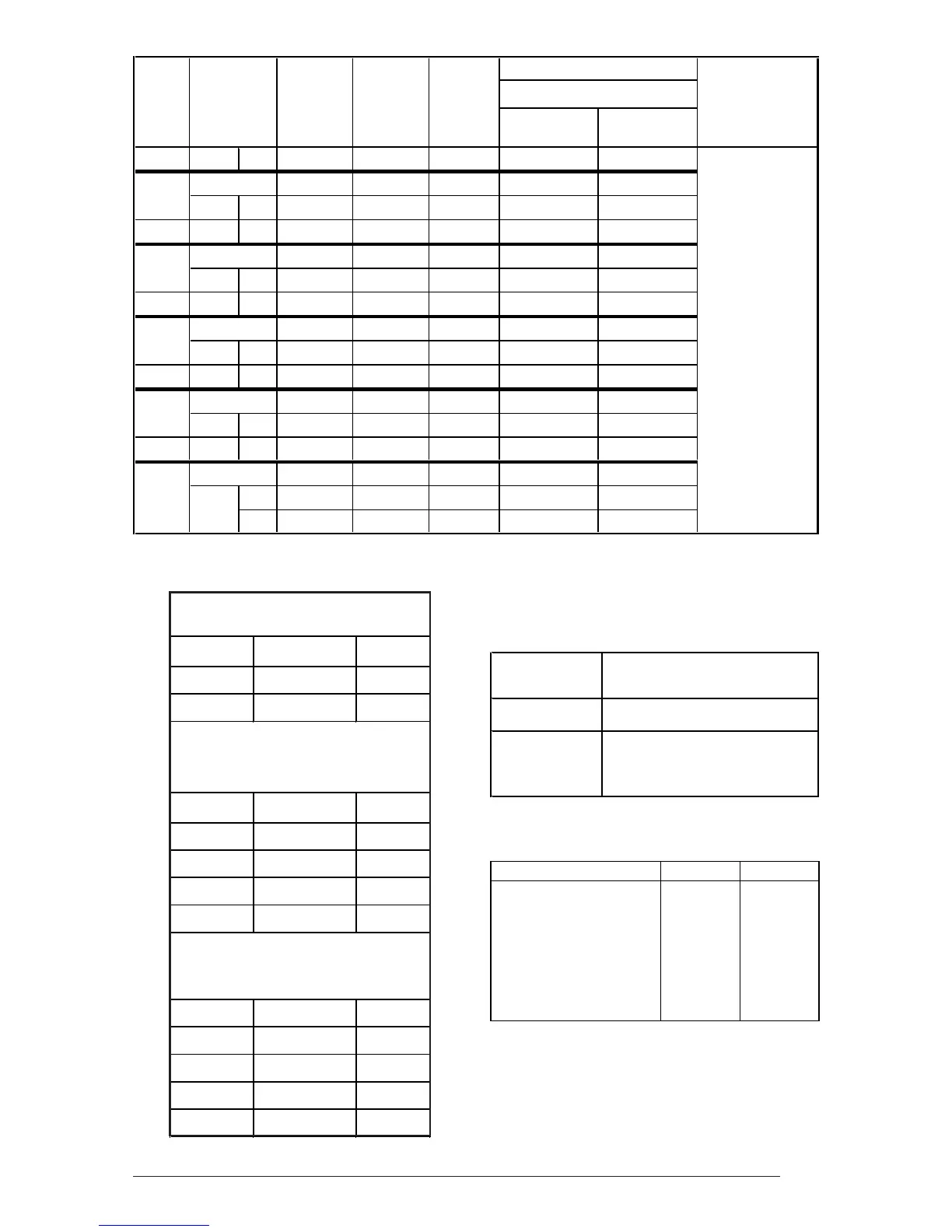
Standard 2-Speed Blower,
with filter, @ 0.3" ESP
Pin No. Speed CFM
#1 Low 840
#2 High 1160
4-Ton Blower with Coil and
Coil Filters, @ 0.3" ESP
Pin No. Speed CFM
#1 Low 880
#2 Med.-Low 1170
#3 Med.-High 1310
#4 High 1460
5-Ton Blower, with Coil and
Coil Filters, @ 0.3" ESP
Pin No. Speed CFM
#1 Low 990
#2 Med.-Low 1320
#3 Med.-High 1620
#4 High 1790
Sizes*
Model Max Over- Min. 75°C Copper Low-Voltage
E2EH/
E2EB-
Supply
Circuit
Total
Amperes
Current
Rating
Circuit
Ampacity Wire Size Ground Size
Thermostat Wire
Size
010
Single
45.5
60 57 6
10
012
Single
52.1
70 65 6
8
Dual "A"
28.0
40 35 8
10
"B"
24.2
30 30 10
10
015
Single
66.3
90 83 4
8
Dual "A"
45.5
60 57 6
10
"B"
20.8
30 26 10
10
017
Single
71.3
90 89 3
8
Dual "A"
48.8
60 61 6
10
"B"
22.5
30 28 10
10
020
Single
87.1
125 109 2
6
Dual "A"
45.5
60 57 6
10
"B"
41.7
60 52 6
10
023
Single
93.8
125 117 1
6
Dual "A"
45.5
60 57 6
10
"B"
48.3
60 60 6
10
2-Wire
system max
wire lengths :
24 Ga. = 55’
22 Ga. = 90’
20 Ga. = 140’
18 Ga. = 225’
4 or more-Wire
system max
wire lengths :
24 Ga. = 25’
22 Ga. = 45’
20 Ga. = 70’
18 Ga. = 110’
Table 6. Electrical Specifications
Table 7. Blower Performance
Table 8. Anticipator Settings
* All wire sizes for copper conductors only, based on NEC Table 310-16. Equivalent wiring may be used per NEC.
Furnace Thermostat
Model Anticipator Setting
010, 012 0.20
015, 017,
020, 023
0.40
ALL MODELS CLOSET ALCOVE
Front ‡ 6" 18"
Back 0" 0"
Sides 0"† 0"†
Top 0" 0"
Top and Sides of Duct 0" 0"
Bottom of Duct 0" 0"
‡ Service Clearance
† For upflow application using upflow stand,
1" minimum per side.
Table 9. Clearances
 Loading...