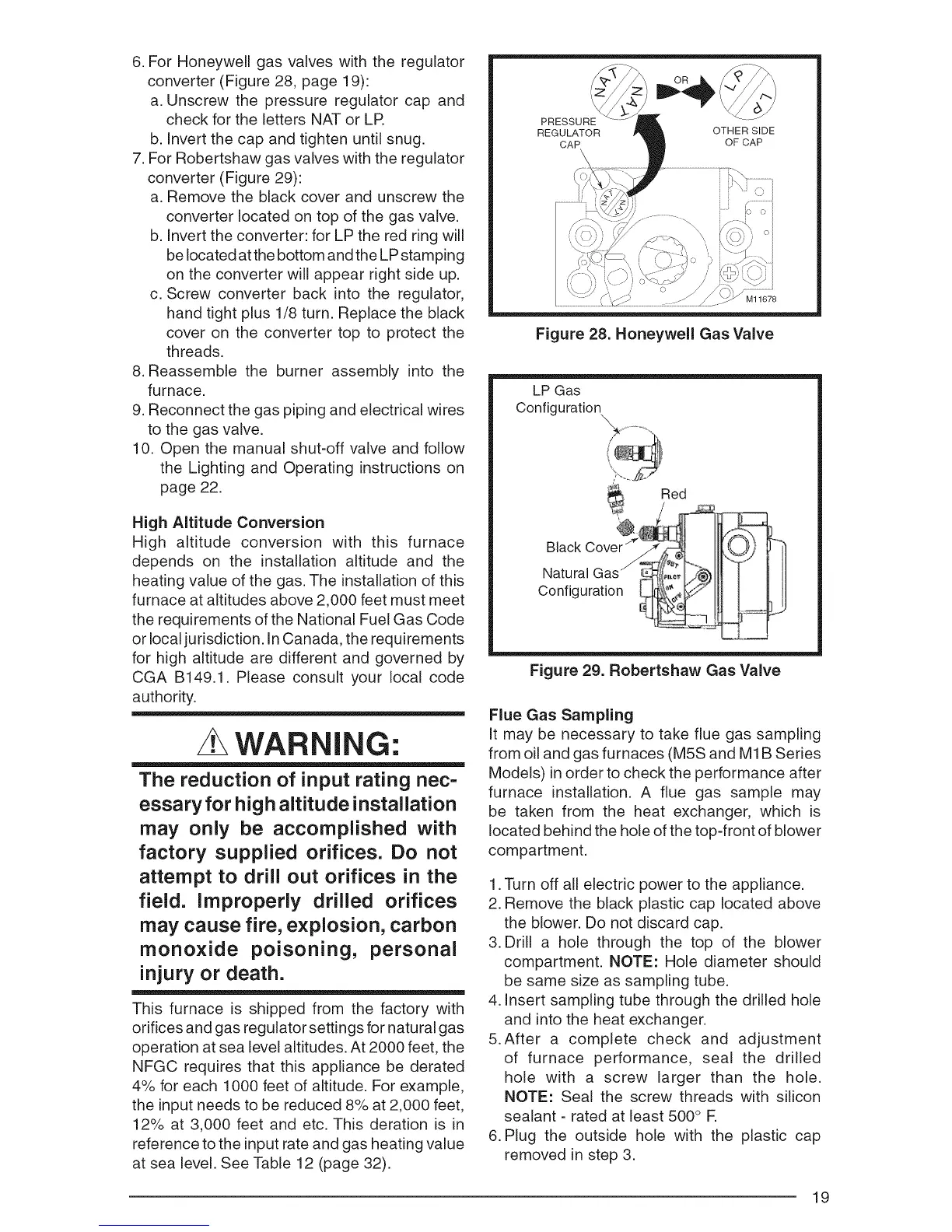
6.ForHoneywellgasvalveswiththe regulator
converter(Figure28,page19):
a.Unscrewthe pressureregulatorcapand
checkforthelettersNATorLR
b.Invertthecapandtightenuntilsnug.
7.ForRobertshawgasvalveswiththeregulator
converter(Figure29):
a.Removetheblackcoverandunscrewthe
converterlocatedontopof thegasvalve.
b.Inverttheconverter:forLPtheredringwill
belocatedatthebottomandtheLPstamping
ontheconverterwillappearrightsideup.
c.Screwconverterbackintothe regulator,
handtightplus1/8turn.Replacetheblack
coveron theconvertertopto protectthe
threads.
8.Reassemblethe burnerassemblyinto the
furnace.
9.Reconnectthegaspipingandelectricalwires
tothegasvalve.
10.Openthe manualshut-offvalveandfollow
the LightingandOperatinginstructionson
page22.
HighAltitude Conversion
High altitude conversion with this furnace
depends on the installation altitude and the
heating value of the gas. The installation of this
furnace at altitudes above 2,000 feet must meet
the requirements of the National Fuel Gas Code
or local jurisdiction. InCanada, the requirements
for high altitude are different and governed by
CGA B149.1. Please consult your local code
authority.
WARNING:
The reduction of input rating nec=
essary for high altitude installation
may only be accomplished with
factory supplied orifices. Do not
attempt to drill out orifices in the
field. Improperly drilled orifices
may cause fire, explosion, carbon
monoxide poisoning, personal
injury or death.
This furnace is shipped from the factory with
orifices and gas regulator settings for natural gas
operation at sea level altitudes. At 2000 feet, the
NFGC requires that this appliance be derated
4% for each 1000 feet of altitude. For example,
the input needs to be reduced 8% at 2,000 feet,
12% at 3,000 feet and etc. This deration is in
reference to the input rate and gas heating value
at sea level. See Table 12 (page 32).
PRESSURE
REGULATOR OTHER SIDE
CAP OF CAP
Ml1678
Figure 28. Honeywell Gas Valve
LP Gas
Configuration
Red
Black Cove ,_}) -"
Natural Gas
Configuration
Figure 29. Robertshaw Gas Valve
Flue Gas Sampling
It may be necessary to take flue gas sampling
from oil and gas furnaces (M5S and M1B Series
Models) in order to check the performance after
furnace installation. A flue gas sample may
be taken from the heat exchanger, which is
located behind the hole of the top-front of blower
compartment.
1. Turn off all electric power to the appliance.
2. Remove the black plastic cap located above
the blower. Do not discard cap.
3. Drill a hole through the top of the blower
compartment. NOTE: Hole diameter should
be same size as sampling tube.
4. Insert sampling tube through the drilled hole
and into the heat exchanger.
5.After a complete check and adjustment
of furnace performance, seal the drilled
hole with a screw larger than the hole.
NOTE: Seal the screw threads with silicon
sealant - rated at least 500 ° R
6. Plug the outside hole with the plastic cap
removed in step 3.
19
 Loading...