co
4_
0
0
O_
3
o
0
0
0
0
Ol
0
0
o
Q.
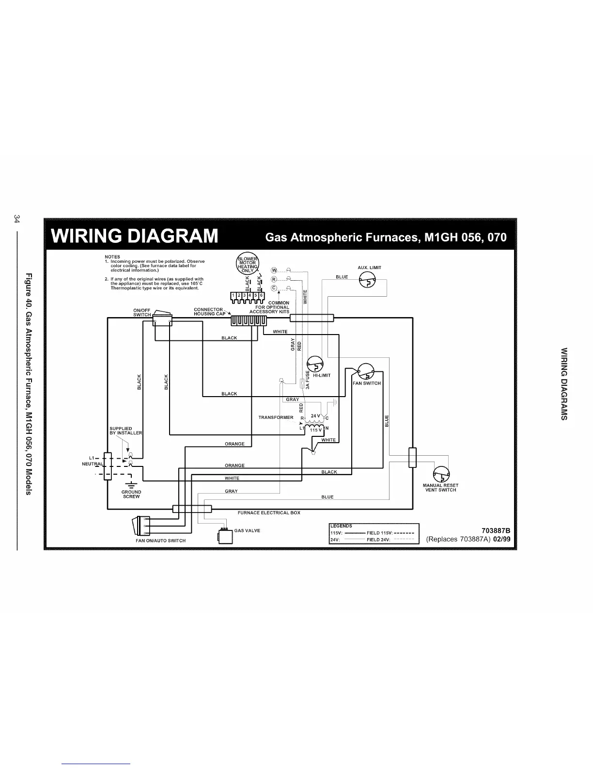
NOTES
I. Incoming power must be polarized. Observe
color coding. (See furnace data label for
electrical information.)
2. If any of the original wires (as supplied with
the appliance) must be replaced, use I05_C
Thermoplastic type wire or its equivalent.
Elm =
NEUTR.AL
o
<,
SUPPLIED
BY INSTALLER
GROUND
SCREW
_i _i ® _ ......
_1 _I t
COMMON
CONNECTOR. FOR OPTIONAL
HOUSING CAP %_, ACCESSORY KITS
I IUIUIUliIUIU_
BLACKII WH,TE
o
AUX. LIMIT
BLUE
I
'I
FAN ON/AUTO SWITCH
BLACK
TRANSFC
ORANGE
ORANGE
WHITE
GRAY
1,
II I' FURNACEELECTRICALBOX
[ _GASVALVE
HI'LIMIT
I BLACK
BLUE
[]
]
FIELD 115V: .......
]
FIELD 24V:
÷
MANUAL RESET
VENT SWITCH
703887B
(Replaces 703887A) 02199
Z
E_
_b
 Loading...