thecadcellisoperational,replacetheprimary
control.
4.If the LEDcontinuesto flashat the interval
listedabove,verifythatthecontrolis notin
restrictedmode.Ifinrestrictedmode,resetit.
If notinrestrictedmode,replacethecontrol.
5.Ifthe(LEDindicatorforR7184control;green
LEDfor7505control)staysoffwhiletheflame
is on,checkthecadcellsightingforviewof
theflame.
6.If the burnerlocksout,checkthe cadcell
resistance.(SeeTable8)
7.If the burnerstaysrunning,the systemis
operational.
8.Ifthe(LEDindicatorforR7184control;green
LEDfor7505control)isoff,checkthecadcell
assemblyafterdisconnectingthelinevoltage.
Burner will not start and the LED indicator is
flashing at 2 seconds on, 2 seconds off for
R7184 (or the green LED is flashing for 7505).
. Hold the reset button down for 1 - 2 seconds.
If LED indicator continues to flash, wait for
60 - 70 seconds. If it still continues to flash,
replace the primary control.
, Honeywell R7184 control: To check cad cell
resistance, press and release the button during
the run mode, with the igniter off.The LED will
flash to indicate the cad ceEEresistance. For
proper burner operation, it is important that
the cad cell resistance is under 1600 Ohms.
For cad cell resistance, see Table 8.
, Beckett 7505 control: To check cad cell
resistance, unplug the cad cell leads (yellow
wires) from the control. Measure the resistance
with a meter in the conventional way (when a
flame is present). For proper burner operation,
it is important that the cad cell resistance is
under 1,600 Ohms.
LED Flashes (Ohms)
1
2
3
4
Cad Cell Resistance
0-400
400-800
800-1600
>1600
Table 8. Cad Cell Resistance when
sensing flame
OPTIONAL ACCESSORIES
Necessary when the Furnace is Used with
Some Central Air Conditioners
If an air conditioner is installed that does not use
the furnace blower for air distribution and operates
independently of the furnace, the thermostat
system must have an interlock to prevent the
furnace and air conditioner from operating at
the same time. This interlock system usually
contains either a "Heat-Cool" switch which must
be turned to one of the positions to activate heat
or cool operation, or a positive "OFF" switch on
the cooling thermostat.
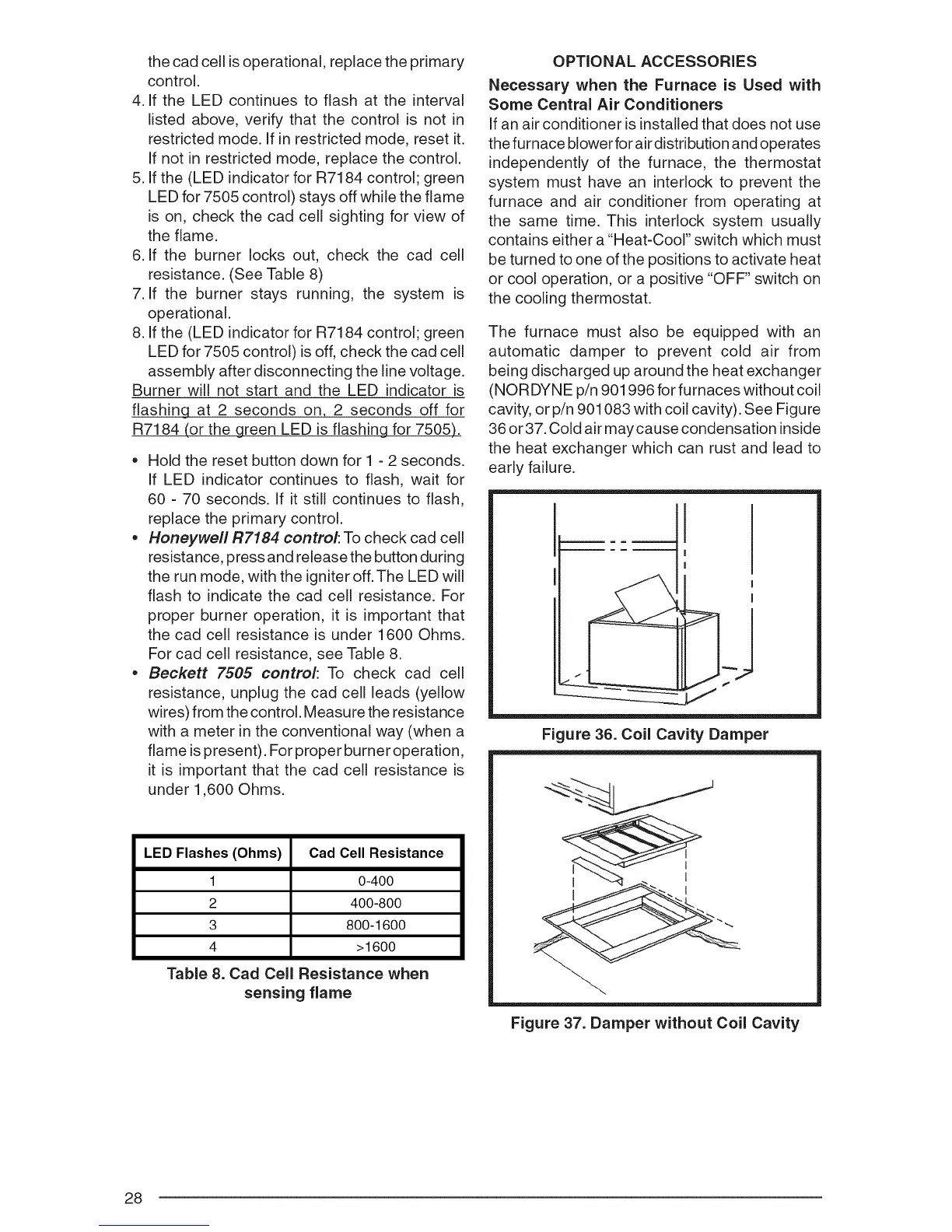
The furnace must also be equipped with an
automatic damper to prevent cold air from
being discharged up around the heat exchanger
(NORDYNE p/n 901996 for furnaces without coil
cavity, or p/n 901083 with coil cavity). See Figure
36 or 37. Cold air may cause condensation inside
the heat exchanger which can rust and lead to
early failure.
I
!
|
I
J
I
Figure 36. Coil Cavity Damper
Figure 37. Damper without Coil Cavity
28
 Loading...