EasyManua.ls Logo

Nordyne SA4BE-024KA Series - User Manual

Nordyne SA4BE-024KA Series
16 pages
Print Icon
To Next Page IconTo Next Page
Loading...
SPLIT SYSTEM AIR CONDITIONER
*S4BE / *SA4BE - 018, 024, 030, 036, 042, 048, & 060 (1.5, 2, 2.5, 3, 3.5, 4, & 5 TON) SERIES
14 SEER, SINGLE PHASE MODELS
IMPORTANT
ATTENTION INSTALLERS:
It is your responsibility to know this product
better than your customer. This includes
being able to install the product according
to strict safety guidelines and instructing the
customer on how to operate and maintain the
equipment for the life of the product. Safety
should always be the deciding factor when
installing this product and using common
sense plays an important role as well. Pay
attention to all safety warnings and any other
special notes highlighted in the manual.
Improper installation of the unit or failure to
follow safety warnings could result in serious
injury, death, or property damage.
These instructions are primarily intended to
assist qualified individuals experienced in the
proper installation of this appliance. Some
local codes require licensed installation/
service personnel for this type of equipment.
Please read all instructions carefully before
starting the installation. Return these
instructions to the customer’s package for
future reference.
DO NOT DESTROY. PLEASE READ CAREFULLY &
KEEP IN A SAFE PLACE FOR FUTURE REFERENCE.
INSTALLATION INSTRUCTIONS
IMPORTANT SAFETY INFORMATION ..................2
AIR CONDITIONER INSTALLATION .....................3
General Information ...............................................3
Before You Install this Unit .....................................3
Locating the Air Conditioner ...................................3
Packaging Removal ............................................... 3
Ground Level .........................................................3
Roof Mount ............................................................3
Connecting Refrigerant Tubing Between the
Indoor & Outdoor Unit ............................................ 3
ELECTRICAL WIRING ...........................................4
Pre-Electrical Checklist ..........................................4
Line Voltage ........................................................... 4
Grounding ..............................................................5
CoreSense
TM
Diagnostics Module ..........................5
Compressor Protection ........................................ 5
Resetting Alert Codes ..........................................5
Thermostat Connections ........................................5
START UP & ADJUSTMENTS ............................... 5
Pre-Start Check List ...............................................5
Start-Up Procedures ..............................................6
Air Circulation - Indoor Blower ............................. 6
System Cooling ....................................................6
System Heating (optional) ...................................6
REFRIGERANT CHARGING .................................. 6
Charging the Unit in AC mode ...............................6
Application Notes & Charging Info ......................... 7
Table 3. Charging Table for 1.5 Ton Models .......7
Table 4. Charging Table for 2 Ton Models ..........8
Table 5. Charging Table for 2.5 Ton Models .......8
Table 6. Charging Table for 3 Ton Models ..........9
Table 7. Charging Table for 3.5 Ton Models .......9
Table 8. Charging Table for 4 Ton Models ..........10
Table 9. Charging Table for 5 Ton Models ..........10
Figure 3. Charging Chart for 2 - 5 Ton Units .......11
AIR CONDITIONER MAINTENANCE .....................11
ELECTRICAL INFORMATION ...............................12
Table 10. LED Diagnostics for CoreSense
TM
Diagnostics Module .............................................12
Figure 4. Wiring Diagram for 1.5 - 4 Ton Models
without CoreSense
TM
) ..........................................12
Figure 5. Wiring Diagram for 1.5 - 4 Ton Models
(with CoreSense
TM
) .............................................13
Figure 6. Wiring Diagram for 5 Ton Models
(without CoreSense
TM
) ........................................14
Figure 7. Wiring Diagram for 5 Ton Models
(with CoreSense
TM
) .............................................15
INSTALLATION CHECKLIST .................................16
REPLACEMENT PARTS ........................................ 16
Question and Answer IconNeed help?

Do you have a question about the Nordyne SA4BE-024KA Series and is the answer not in the manual?

Summary

Important Safety Information

Air Conditioner Installation

Connecting Refrigerant Tubing Between the Indoor & Outdoor Unit

Guidelines for routing refrigerant tubing between indoor and outdoor units for proper system connection.

Electrical Wiring

Grounding

Start Up & Adjustments

Start-Up Procedures

Refrigerant Charging

Charging the Unit in AC mode

Method for charging the unit in air conditioning mode at outdoor temperatures above 65°F.

Air Conditioner Maintenance

Wiring Diagram

Figure 4. Wiring Diagram for 1.5 - 4 Ton Models (without CoreSense)

Schematic illustrating electrical connections for 1.5-4 ton models without CoreSense.

Figure 5. Wiring Diagram for 1.5 - 4 Ton Models (with CoreSense)

Schematic illustrating electrical connections for 1.5-4 ton models with CoreSense.

Figure 6. Wiring Diagram for 5 Ton Models (without CoreSense)

Schematic illustrating electrical connections for 5 ton models without CoreSense.

Figure 7. Wiring Diagram for 5 Ton Models (with CoreSense)

Schematic illustrating electrical connections for 5 ton models with CoreSense.

Installation Checklist

Overview

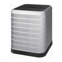
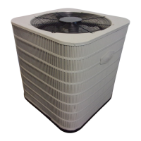
This document provides comprehensive installation and maintenance instructions for the S4BE / *SA4BE split system air conditioner, covering 1.5 to 5-ton single-phase models. It emphasizes safety, proper installation techniques, and routine maintenance to ensure optimal performance and longevity of the unit.

Function Description

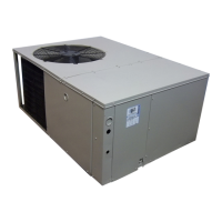
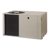
The S4BE series air conditioner is designed for outdoor rooftop or ground-level installations, providing safe and dependable comfort. It operates by circulating refrigerant between an indoor and outdoor unit to cool or, optionally, heat an indoor space. The system includes a compressor, outdoor fan motor, and various electrical components that work in conjunction with an indoor blower (air handler or furnace) to condition the air. The CoreSense™ Diagnostics Module (on select models) is an innovative feature that helps troubleshoot system and compressor fault conditions by providing diagnostic codes via a flashing LED indicator. This module also offers compressor protection through proprietary algorithms that safeguard against repeated trips of system pressure controls and internal overload.

Usage Features

The unit is designed for ease of use once properly installed. Operation is primarily controlled via a thermostat, allowing users to set the desired temperature and fan mode (AUTO or ON). The system automatically cycles the compressor and outdoor fan to maintain the set temperature. For cooling, the thermostat is set to COOL mode, and the temperature is lowered below room temperature. For optional heating, the thermostat is set to HEAT mode, and the temperature is raised above room temperature. The indoor blower circulates conditioned air throughout the space.

The CoreSense™ Diagnostics Module enhances usability by simplifying troubleshooting. In the event of a system fault, the module's LED will flash a specific alert code, which can be referenced in the manual's diagnostic key to quickly identify the root cause of the problem. This reduces the time and effort required for service technicians to diagnose and resolve issues. The module also includes a reset button to clear alert codes after a fault has been resolved, restoring normal operation.

Maintenance Features

Routine maintenance is crucial for the optimal performance and longevity of the S4BE / *SA4BE air conditioner. The manual outlines several key maintenance tasks that should be performed regularly.

Pre-Installation and Installation Maintenance:

  • Inspection: Before installation, all units should be carefully inspected for damage. Coil fins should be checked and straightened if bent.
  • Clearances: Maintaining sufficient clearance around the outdoor unit for unobstructed airflow is critical. Overhead obstructions and poorly ventilated areas should be avoided.
  • Mounting Pad: For ground-level installations, a level and strong mounting pad, at least 2 inches above grade with adequate drainage, is required.
  • Roof Mount: For roof installations, the mounting method must prevent overloading roof structures and noise transmission. Full perimeter support made of weather-resistant materials is necessary, raising the unit 6 inches above the roof.
  • Refrigerant Tubing: Refrigerant linesets should be routed to minimize length and bends, supported to prevent vibration, and kept clean of debris. A filter dryer, provided with the unit, must be installed in the liquid line.
  • Electrical Wiring: All electrical connections must comply with local and national codes. An electrical disconnect must be located within sight and readily accessible to the unit. Line voltage wiring should use copper conductors of appropriate gauge, and the unit must be properly grounded.

Start-Up and Adjustment Maintenance:

  • Pre-Start Checklist: Before initial start-up, verify that the indoor unit is level, the outdoor coil and top of the unit are free from obstructions, air filters are clean, ductwork is sealed, and all electrical connections (line voltage and low voltage) are secure and correctly wired.
  • Air Circulation Check: Verify continuous blower operation in ON mode and proper air delivery at registers.
  • System Cooling Check: Confirm that the outdoor unit and indoor blower energize, and the circulated air is cooler than ambient temperature. Listen for unusual noises and verify proper cycling with the thermostat.
  • System Heating Check (optional): Confirm that heating equipment and indoor blower energize, and the circulated air is warmer than ambient temperature.
  • Refrigerant Charging: If evacuation and charging are necessary, it should only be performed by qualified personnel. The manual provides detailed charging tables and charts (Figure 3, Tables 3-9) for various ton models and outdoor temperatures to ensure the correct liquid refrigerant pressure. This involves measuring liquid refrigerant pressure and temperature at the service valve and comparing it to the charging chart to add or remove refrigerant as needed.

Routine Maintenance:

  • Air Filters: Inspect, clean, or replace air filters at the beginning of each heating and cooling season, or more frequently if required. This is crucial for maintaining indoor air quality and system efficiency. The unit should never be operated without a filter in the return air system.
  • Condensate Drain and Outdoor Coil: Inspect and clean the condensate drain and outdoor coil at the beginning of each cooling season. Remove any debris. The outdoor coil and louvers should be cleaned with a mild detergent and water, then thoroughly rinsed.
  • Electrical Connections: Inspect electrical connections for tightness at the beginning of each heating and cooling season and service as necessary.
  • Compressor Lubrication: Do not attempt to add additional oil to motors unequipped with oil tubes. The compressor is hermetically sealed at the factory and does not require lubrication.

The manual stresses that only qualified individuals experienced in appliance installation should attempt to install or service this equipment. Failure to follow safety warnings and proper installation/maintenance procedures could result in serious injury, death, or property damage. It is recommended to keep these instructions for future reference and consult a dealer for maintenance information and contracts.

Nordyne SA4BE-024KA Series Specifications

General IconGeneral
BrandNordyne
ModelSA4BE-024KA Series
CategoryAir Conditioner
LanguageEnglish

Related product manuals