Do you have a question about the Nordyne 16 SEER and is the answer not in the manual?
Comprehensive guide for operating and installing the two-stage R-410A split system air conditioner.
Crucial introductory section with safety warnings and operational advice before using the unit.
Explains safety markings and potential hazards associated with the unit.
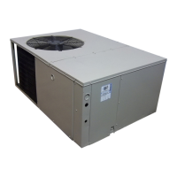
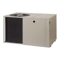
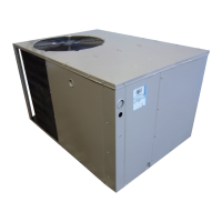
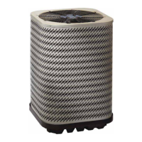
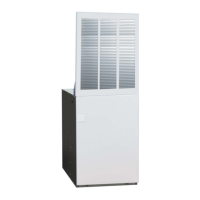
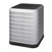
Overview of the 16 SEER air conditioner's design and components.
Details the advantages of split systems and two-stage variable speed cooling.
Guides on how to operate the unit for cooling and heating modes using the thermostat.
Procedures for continuous indoor blower operation and proper unit shutdown.
Outlines warranty details, responsibilities, and exclusions for service calls.
Guidelines for annual maintenance, cleaning air filters, and clearing outdoor unit coils.
Initial checks for common AC failures, including thermostat settings and power supply.
Critical safety advice for installers, emphasizing qualified personnel and avoiding hazards.
Warnings about refrigerant, electrical work, brazing, and adherence to local codes.
Overview of split systems and the importance of periodic maintenance.
Steps for unpacking, inspecting for damage, and preparing the unit for installation.
Guidance on selecting the best location and facility requirements for the outdoor unit.
Information on minimum circuit ampacity, breaker size, and mounting options (slab, cantilever).
Details on installing the unit on a stable, level slab foundation.
Guidelines for securing the unit to a cantilever mount with adequate safety factors.
Instructions and warnings for mounting the unit on a roof structure.
Guidelines for routing tubing, handling R-410A refrigerant, and safety during brazing.
Instructions for filter dryer installation and optional equipment per manufacturer's guidelines.
Checklist for verifying voltage, phase, and supply capacity before electrical connections.
Guidance on using wiring diagrams, connecting line voltage, and adhering to electrical codes.
Details on connecting the outdoor unit's power and the 24 VAC control circuit wiring.
Explains the function and operation of the low-pressure switch for compressor protection.
Explains the function and operation of the high-pressure switch for compressor protection.
Description of how the 2-speed outdoor fan motor operates in different cooling modes.
Instructions for wiring the 24 VAC power supply to the Comfort Alert module.
Guidelines for connecting the thermostat demand signal to the Comfort Alert module.
Explains how to interpret LED indicators for system diagnostics and troubleshooting.
Describes the function of the Power, Alert, and Trip LEDs on the diagnostic module.
Instructions for optional equipment wiring and the critical importance of proper unit grounding.
A checklist to ensure correct installation before applying power, covering unit level and wiring.
Initial setup steps for the thermostat and outdoor unit before startup.
Procedures to test cooling and heating operations by adjusting thermostat settings.
Steps to verify the indoor blower operation and airflow.
Procedure to verify the functionality of the compressor and blower short cycle protection.
Guidance for performing functional checkouts on optional equipment.
Critical warnings and notes for qualified personnel regarding refrigerant charge adjustment.
Detailed steps for charging the R-410A system in AC mode using liquid pressure and temperature.
Chart to determine correct refrigerant charge for 2-ton units based on liquid temperature and pressure.
Chart to determine correct refrigerant charge for 3-ton units based on liquid temperature and pressure.
Chart to determine correct refrigerant charge for 4-ton units based on liquid temperature and pressure.
Chart to determine correct refrigerant charge for 5-ton units based on liquid temperature and pressure.
Table correlating LED status indicators with specific system faults and troubleshooting steps.
Detailed troubleshooting for LED flash codes related to compressor problems like short cycling and locked rotors.
Guide to identify and resolve common diagnostic module wiring errors based on LED behavior.
| SEER | Up to 16 |
|---|---|
| Refrigerant Type | R-410A |
| Compressor Type | Scroll |
| Cooling Capacity | 1.5 - 5 Tons |
| Warranty | 10 Years Limited |