Do you have a question about the Nordyne R4GD Series and is the answer not in the manual?
Inspect unit for damage after unpacking and file claims with carrier.
Installer must comply with all local codes and national standards for installation.
Choose outdoor location for unit to minimize duct length and ensure service access.
Unit has integral venting system and must be vented outdoors.
Follow precautions in literature, on tags, and on labels provided with the unit.
Unit contains high pressure refrigerant; service by qualified personnel only.
Verify unit model is correct for job; not for temporary heating.
Install on a level concrete pad at least 2" above grade in a well-draining area.
Use adequate lifting equipment and spreader bars; keep unit upright.
Use appropriate accessory roof curb and follow instructions; ensure roof can handle weight.
Steps to convert unit from horizontal to downflow duct connections.
Field adjustment of manifold pressure and orifice changes for high altitudes.
Adjust manifold pressure for altitudes between 5000-10000 ft.
Convert unit to LP/Propane gas using approved kits and following specific instructions.
Electrical wiring must comply with NEC/CSA codes and unit rating plate.
Verify supply voltage, frequency, phase, and capacity match unit requirements.
Verify unit is level, airflow is clear, ductwork is sealed, and wiring is secure.
Check for air delivery at the register(s). Ensure no obstructions.
Steps to safely shut off the gas supply to the appliance.
Proves flame presence to the ignitor; shuts down unit if no flame is sensed.
Detects flame not drawn into heat exchanger tubes; opens to shut down unit.
Controls the flow of gas to the burners and regulates manifold pressure.
Verifies inducer motor draws combustion gases through the vent system.
Prevents air temperature from exceeding maximum outlet air temperature.
Sequence of operation for the unit in cooling mode.
Sequence of operation for the unit in blower-only mode.
Sequence of operation for the unit in heating mode.
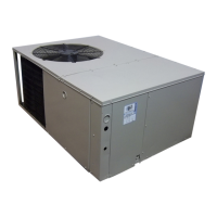
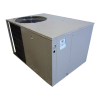
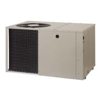
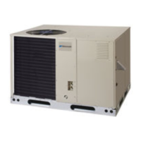
This document provides installation and maintenance instructions for a high-efficiency single-package gas heating/electric cooling unit, designed for outdoor rooftop or ground-level slab installations. The unit is shipped ready for horizontal duct connections and can be easily converted for downflow connections. It comes equipped with a multispeed fixed torque variable speed blower and 24V fuse protection.
The unit provides both heating and cooling capabilities. In heating mode, it utilizes gas combustion to generate warm air, which is then circulated throughout the building. The electric cooling function uses a refrigeration cycle to cool the air. The integrated control system manages the operation of various components, including the blower, gas valve, ignitor, and safety controls, to ensure efficient and safe performance in both modes.
| Series | R4GD |
|---|---|
| Refrigerant Type | R-410A |
| Voltage | 208/230V |
| Phase | 1 |
| Type | Air Conditioner |
| Maximum Overcurrent Protection | Varies by model |
| Minimum Circuit Ampacity | Varies by model |
| Operating Temperature Range (Cooling) | 55°F |
| Dimensions (Outdoor Unit) | Varies by model |
| Weight (Outdoor Unit) | Varies by model |