7
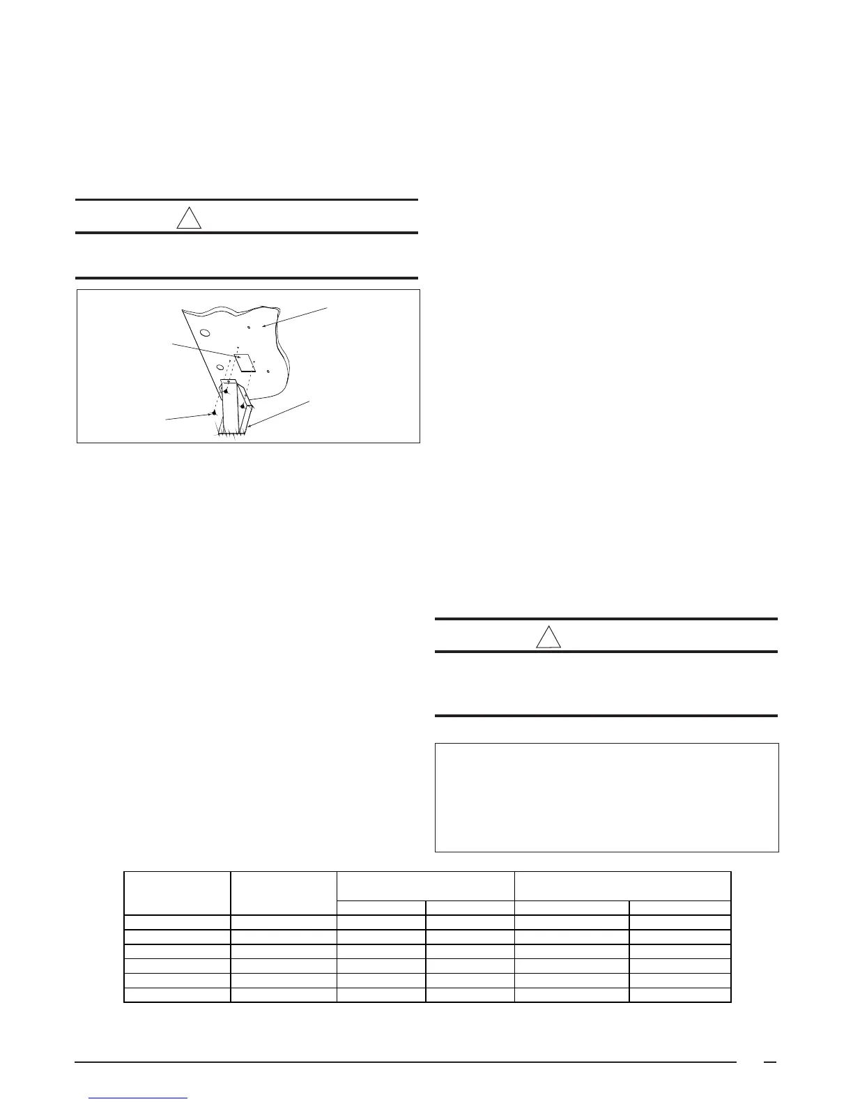
A vent cover assembly has been supplied with the unit. It
can be found secured to the gas controls within the control
area of this unit. Figure 2 shows the proper installation of
the vent cover assembly over the vent outlet on the exterior
of the corner panel. The fasteners used to secure the vent
cover assembly have been included in the homeowner's
package.
WARNING:
The vent cover assembly must be installed to
assure proper operation of the unit.
The following list is a summary of the requirements for the
location of the termination of the venting system:
1. The location of the vent termination must be consistent
with the National Fuel Gas Code (ANSI Z223.1) or CAN/
CGA-B149 Installation Codes.
2. The vent termination must be located at least four (4)
feet horizontally from any electric meters, gas meters,
regulators, and relief equipment.
3. The vent termination must be located at least three (3) feet
above any forced air inlet located within ten (10) feet.
4. The vent termination must be located at least four (4) feet
below, four (4) feet horizontally from, or one (1) foot above any
door, window, or gravity air inlet into any building.
5. The vent termination must be located at least one (1)
foot above grade.
6. The unit should be installed in such a manner as to
prevent snow accumulation from obstructing the vent
termination.
7. The unit installation shall avoid areas where condensate
drainage may cause problems by dropping on planters
or patios, etc. Furthermore, ensure that the exhaust
gases will not impinge on windows or building surfaces,
which may be compromised or damaged by
Table 1. Air Filter Requirements
Figure 2. Vent Assembly
Corner Panel
of Unit
Vent Cover
Assembly
Fastener
Exhaust Duct
Opening
IMPORTANT NOTICE TO INSTALLER: After installing
or replacing the filtration system for this unit, add the
following marking on the filter service panel or reasonably
adjacent thereto: “Replace filter(s) installed in your
system only with the same dimensional size filters
that are being replaced.”
condensation. Do not install the unit such that exhaust
from the vent termination is directed into window wells,
stairwells, under decks, or in alcoves or similarly
recessed areas. The vent termination must not be
located above any public walkways.
Clearances to Combustible Materials — See Table 2 for
required clearances to combustible materials. Refer to the
unit data label for the model number. The gas/electric unit
is suitable for installation on combustible flooring or class
A, B, or C roofing materials. A clearance of at least 36
inches from the blower access panel and from the louvered
control access panel is recommended to allow for servicing
and maintenance. Where accessibility to combustibles
clearances are greater than minimum clearances,
accessibility clearances must take preference. Sufficient
clearance for unobstructed airflow through the louvered
control access panel and through the outdoor coil must be
maintained in order to achieve rated performance. See
Figure 3 for minimum clearances to obstructions.
Thermostat — A single stage cooling/single stage heating
24VAC thermostat should be used with these units. A two-
stage cooling/single-stage heating thermostat is
recommended for economizer operation.
Air Filter Requirements — A suitable air filter system
must be installed in the unit or in the return air system
upstream of the evaporator coil. Refer to Table 1 for
recommended filter sizes. Air filter pressure drop must not
exceed 0.08 inches WC. This unit is not supplied with air
WARNING:
Never operate unit without a filter. A failure to
follow this warning could result in a fire, personal
injury, or death.
Nominal Approximate Approximate Recommended
Cooling Air Flow Range Filter Area (Sq. In.)* Filter Size (In. x In.)
Tonnage (Ton) (CFM) Disposable High Velocity Disposable High Velocity
2.0 600-1200 450 275 20 x 25 15 x 20
2.5 600-1200 550 325 20 x 30 16 x 20
3.0 800-1250 625 375 25 x 25 20 x 20
3.5 850-1500 725 450 24 x 30 20 x 25
4.0 1050-1650 825 500 18 x 24 (2 required) 20 x 25
5.0 1050-1650 1000 600 20 x 25 (2 required) 25 x 25
*Based on velocity of 300 ft/min for disposable filters and 500 ft/min for high velocity (cleanable) filters.
 Loading...