Do you have a question about the Nordyne NS6QD SERIES and is the answer not in the manual?
Safety markings and warnings for potential hazards.
How to operate the unit for cooling, heating, and fan modes.
Guidelines for routine maintenance for optimal performance.
Steps to diagnose and resolve common unit issues.
Critical safety warnings for installation and servicing.
Procedures and considerations for installing the unit.
Overview of key components and their roles in the system.
Information on obtaining and ordering replacement parts.
References to diagrams and data tables for unit specifications.
A checklist to ensure proper installation and initial performance.
Design purpose, performance, and maintenance recommendations.
Pre-installation checks for load, electrical supply, and unit inspection.
Site selection criteria for optimal unit placement and airflow.
Instructions for safely removing packaging from the unit.
Requirements for ground level installations, including pad specifications.
Warning regarding refrigerant oil and system exposure to air.
Table specifying torque values for coupling connections.
Warning about electrical shock hazards during maintenance.
Checklist for verifying electrical supply and connections before wiring.
Table showing copper wire sizes based on length and ampacity.
Warning about the necessity of proper electrical grounding.
Table for recommended thermostat wire gauge and lengths.
Checklist of items to verify before starting the unit.
Step-by-step guide for initiating system operation.
Procedures for checking and adjusting indoor blower operation.
Steps for verifying and testing the cooling system performance.
Procedures for verifying and testing the optional heating system.
Instructions and warnings for properly charging the refrigerant system.
Warning about electrical shock hazards during maintenance.
Caution regarding unit operation without a filter and motor oil.
Explanation of the high-pressure switch function and operation.
Lists electrical replacement parts available for the unit.
Lists motor replacement parts available for the unit.
Lists other component replacement parts available for the unit.
Diagram showing the physical dimensions of the unit.
Table detailing electrical specifications and physical data for various models.
Wiring diagram for single-phase split system air conditioners.
Schematic showing wiring for 2-2.5 ton NS6QD units.
Wiring diagram for single-phase split system air conditioners.
Schematic showing wiring for 3 ton NS6QD units.
Wiring diagram for single-phase split system air conditioners.
Schematic showing wiring for 3.5-5 ton NS6QD units.
Guidance on using charging charts for system performance.
Chart for determining refrigerant charge for 2-ton units.
Chart for determining refrigerant charge for 2.5-ton units.
Chart for determining refrigerant charge for 3-ton units.
Chart for determining refrigerant charge for 3.5-ton units.
Chart for determining refrigerant charge for 4-ton units.
Chart for determining refrigerant charge for 5-ton units.
Field for inputting the installation location details.
Checks related to the unit's refrigeration system operation.
Checks related to the unit's electrical system connections and voltage.
Field to record blower motor specifications and calibration checks.
Confirmation of thermostat calibration status.
Confirmation of thermostat mounting level.
Confirmation of heat anticipator setting.
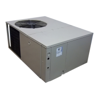
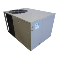
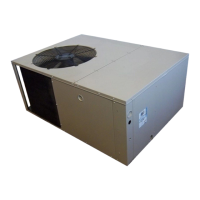
This document is a user's manual and installation instructions for the NS6QD Series outdoor split system air conditioner, designed for manufactured housing. It provides comprehensive information for both users and installers to ensure safe, efficient, and long-lasting operation of the unit.
The NS6QD Series air conditioner is designed to provide cooling and, with optional equipment, heating for manufactured homes. It operates as an outdoor split system, meaning it works in conjunction with an indoor unit (air handler or furnace) to circulate conditioned air throughout the living space. The system utilizes R-410A refrigerant and is designed for ground-level or rooftop installations. Its primary function is to maintain a desired indoor temperature, offering both cooling and, when paired with appropriate indoor heating equipment, heating capabilities. The unit is designed for automatic operation, where it cycles on and off as needed to maintain the set temperature.
The air conditioner's operation is controlled via a thermostat, which allows users to select system modes (COOL, HEAT, AUTO, OFF) and fan modes (AUTO, ON), as well as set the desired temperature.
Proper and frequent maintenance is crucial for optimal performance and longevity of the NS6QD Series air conditioner. The manual outlines several key maintenance tasks, emphasizing that these should ideally be performed by qualified, trained personnel due to the presence of pressurized refrigerants and electrical components.
The manual also stresses the importance of adhering to all local codes and regulations for installation and servicing, and warns against unqualified individuals attempting to install or service the equipment to prevent personal injury, property damage, or death. It also provides a list of replacement parts available through distributors, including electrical components (capacitors, compressors, contactors, relays, switches, transformers), motors (blower and fan), and other components (blower assembly, cabinet panels, expansion valves, fan grille, filter/driers).
| Series | NS6QD |
|---|---|
| SEER | Up to 16 |
| Voltage | 208/230V |
| Phase | 1 |
| Refrigerant Type | R-410A |
| Type | Air Conditioner |