Split System Heat Pump
FT4BG & PSH4BG Series
INSTALLATION INSTRUCTIONS
18 SEER
The 18 SEER, iQ Drive
®
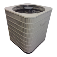
split heat pump operates as part of a larger system which can provide temperature, air flow, and
humidity control for a residence or other similarly sized building. This system includes this outdoor unit and a compatible
indoor unit, typically an air handler with electric strip heat or a gas furnace. The electric or gas heat may serve as backup
or auxiliary heat to supplement the heat pump, which is expected to serve as the primary heating means. However, electric
or gas heat is not required for this system to operate. Accessory equipment which may be used with the system includes
humidifiers, electric or electronic air cleaners, and U/V (ultraviolet) sterilizing lamps.
Refer to the System Operation section within this document for a description of how the heat pump operates. In addition,
information for troubleshooting and diagnosing problems is included.
OTHER REFERENCE DOCUMENTS
• Installation instruction documents for indoor equipment
(furnace or air handler, optional humidifier, etc.)
• localwiringandbuildingcodes
• NordyneApplicationGuidelineforRefrigerantLinesOver
75 Feet, document 044B-0600
• Operation/congurationmanualfortwo-stagethermostat
(existing or newly installed)
DO NOT DESTROY. PLEASE READ CAREFULLY AND
KEEP IN A SAFE PLACE FOR FUTURE REFERENCE.
IMPORTANT
ATTENTION INSTALLERS:
It is your responsibility to know this product
better than your customer. This includes being
able to install the product according to strict
safety guidelines and instructing the customer
on how to operate and maintain the equipment for
the life of the product. Safety should always be
the deciding factor when installing this product
and using common sense plays an important
role as well. Pay attention to all safety warnings
and any other special notes highlighted in the
manual. Improper installation of the furnace or
failure to follow safety warnings could result in
serious injury, death, or property damage.
These instructions are primarily intended to
assist qualified individuals experienced in the
proper installation of this appliance. Some
local codes require licensed installation/service
personnel for this type of equipment. Please
read all instructions carefully before starting
the installation. Return these instructions to the
customer’s package for future reference.
IMPORTANT SAFETY INFORMATION ........................2
PREPARATION ............................................................. 3
Slab Mounting ..............................................................3
Roof Mounting ..............................................................3
ELECTRICAL CONNECTIONS ....................................4
Electrical Power Wiring ................................................4
Control Circuit Wiring ...................................................4
REFRIGERANT LINE CONNECTIONS ........................4
LineDesignandRouting ..............................................4
Brazing ......................................................................... 5
System Evacuation ......................................................5
Refrigerant Charging ....................................................5
Charging Operation ......................................................5
Alternate Procedure for Charging a Heat Pump
in Cooling Mode ...........................................................6
Alternate Procedure for Charging a Heat Pump
in Heating Mode ........................................................... 6
SYSTEM OPERATION ..................................................6
Thermostat ...................................................................6
Run Sequence .............................................................6
Blower Flow Rates .......................................................7
Delay Override .............................................................7
Defrost Cycle................................................................7
Auxiliary Heat ............................................................... 7
Diagnostic Display ........................................................7
Instrumentation ............................................................7
MAINTENANCE ............................................................ 8
FIGURES & CHARTS ...................................................9
Figure 2. Heat Pump Control Panel ...........................9
Figure 3. Power Wiring Terminals .............................10
Figure4.LowVoltageCompartment ........................ 10
Figure 5. Service Valves ...........................................10
Figure 6. Charging Charts ........................................11
Figure 7. Interface Board in Control Panel ...............12
Figure 8. Wiring Diagram (2-4 Ton Models) ..............13
Figure 9. Wiring Diagram (5 Ton Models) ................. 14
Figure 10. Temperature Sensor Resistance Carts ...15
INSTALLATION / PERFORMANCE CHECK LIST .....16




 Loading...