EasyManua.ls Logo

Nordyne JS4BD-KA Series User Manual

Nordyne JS4BD-KA Series
16 pages
To Next Page IconTo Next Page
Page #1 background imageLoading...
Page #1 background image
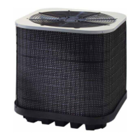
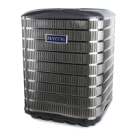
13 SEER R-410A High Effi ciency Split System
These units have been designed and tested for
capacity & effi ciency in accordance with A.H.R.I.
Standards. Split System Air Conditioning units
are designed for use with a wide variety of fossil
fuel furnaces, electric furnaces, air handlers, and
evaporator coil combinations.
Outdoor Air Conditioner
User’s Information and Installation Instructions
These instructions are primarily intended to assist
qualifi ed individuals experienced in the proper
installation of heating and/or air conditioning
appliances. Some local codes require licensed
installation/service personnel for this type of
equipment. Read all instructions carefully before
starting the installation.
USER’S INFORMATION
IMPORTANT
Read this owner information to become familiar
with the capabilities and use of your appliance.
Keep this with literature on other appliances
where you have easy access to it in the future.
If a problem occurs, check the instructions
and follow recommendations given. If these
suggestions don’t eliminate your problem, call
your servicing contractor .
OPERATING INSTRUCTIONS
To Operate Your Air Conditioner for
Cooling —
1. Set the thermostat system switch to COOL
or AUTO and the thermostat fan switch to
AUTO. (See Figure 1)
2. Set the thermostat temperature to the
desired temperature level by pressing the
WARMER or COOLER button. Please refer
to the separate detailed thermostat user’s
manual for complete instructions regarding
thermostat programming. The outdoor unit
and indoor blower will both cycle on and
off to maintain the indoor temperature at
the desired cooling level.
To Operate Your Furnace for
Heating —
1. Set the thermostat system switch to HEAT
or AUTO and the thermostat fan switch to
AUTO. (See Figure 1)
2. Set the thermostat temperature to the
desired temperature level by pressing the
WARMER or COOLER button. Please refer
to the separate detailed user’s manual
for complete thermostat programming
instructions. The furnace and indoor blower
will cycle on and off to maintain the indoor
temperature at the desired heating level.
To Shut Off Your Air Conditioner —
Set the thermostat system switch to OFF and the
thermostat fan switch to AUTO. (See Figure 1)
The system will not operate, regardless of the
thermostat temperature setting.
To Operate the Indoor Blower
Continuously —
Set the thermostat fan switch to ON (See
Figure 1)
Figure 1. Typical Thermostat
TEMPERATURE
SENSOR
FAN
SWITCH
SYSTEM
MODE
Question and Answer IconNeed help?

Do you have a question about the Nordyne JS4BD-KA Series and is the answer not in the manual?

Nordyne JS4BD-KA Series Specifications

General IconGeneral
BrandNordyne
ModelJS4BD-KA Series
CategoryAir Conditioner
LanguageEnglish

Summary

User Information and Operation

Important Owner Information

Guidance for owners to understand appliance capabilities and use, including troubleshooting steps.

Operating the Air Conditioner for Cooling

Steps to set the thermostat for cooling mode and achieve desired temperature.

Operating the Furnace for Heating

Steps to set the thermostat for heating mode and achieve desired temperature.

Shutting Off the Air Conditioner

Procedure to turn off the air conditioner system via thermostat settings.

Continuous Indoor Blower Operation

Instructions for setting the thermostat to run the indoor blower continuously.

Maintenance and General Information

Regular Air Conditioner Maintenance

Routine tasks for maintaining the air conditioner, including filter cleaning and coil inspection.

Maintenance Before Cooling Season

Specific maintenance task to perform before the cooling season begins, involving motor oiling.

Pre-Service Checks

Essential checks to perform before calling a service technician for assistance.

R-410A Refrigerant Caution

Warning regarding the use of R-410A refrigerant only and the damage from alternatives.

Condensing Unit and Piping Details

Information on the condensing unit, refrigerant lines, and installation requirements.

Electrical Power Supply Requirements

Details on electrical power supply, compliance with codes, and conductor sizing.

Installation Site and Unit Preparation

Corrosion Prevention Notice

Notice regarding stainless steel panels and corrosion prevention in coastal areas.

Safety Considerations During Installation

Important safety guidelines regarding refrigerant pressures, labels, and brazing operations.

Site Preparation Steps

Procedures for unpacking, inspecting equipment, and preparing the installation site.

Outdoor Unit Installation Locations

Guidelines for selecting the preferred location for the outdoor unit installation.

Outdoor Unit Mounting Options

Details on different mounting methods for the outdoor unit: slab, cantilever, and roof.

Indoor Unit Installation

Instructions for installing the indoor unit section prior to refrigerant piping.

Refrigerant Tubing and Electrical Connections

Connecting Refrigerant Tubing

Guidelines for routing and connecting refrigerant tubing between indoor and outdoor units, including filter dryer.

Electrical Connection Procedures

Steps for making electrical connections, including wiring diagrams, control circuits, and power wiring.

Minimum Circuit Ampacity Requirements

Information on minimum circuit ampacity for electrical wiring to the equipment.

Electrical Specifications and Startup

Maximum Fuse and Circuit Breaker Size

Guidance on selecting the correct maximum fuse or circuit breaker size for the outdoor unit.

Disconnect Switch Requirement

Requirement for a disconnect switch within line of sight of the outdoor unit.

Optional Electrical Equipment Wiring

Instructions for wiring optional equipment in accordance with codes and manufacturer's guidance.

Startup and Functional Checkout

Procedures for starting up the unit and performing a functional checkout, including safety warnings.

Indoor Blower and Time Delay Relay

Checking the indoor blower operation and details on the blower time delay relay function.

System Protections and Diagnostics

Low and High-Pressure Switch Functions

Explanation of low and high-pressure switches and their role in system protection.

Comfort Alert Diagnostics Module

Overview of the Comfort Alert diagnostics module for troubleshooting system failures.

Diagnostic LED Indicators

Description of ALERT and TRIP LEDs, their functions, and interpretation of flash codes.

Troubleshooting System Operation

Guidance on interpreting diagnostic LEDs and performing basic cooling checks.

Operational Checks and Notes

Cooling Operation Verification

Steps to verify proper cooling operation by checking airflow and temperature.

Heating Operation Verification

Steps to verify proper heating operation, including blower and equipment energization.

Notes on Other Heating Sources

Important note regarding the functional checking of other heating sources interfacing with the unit.

Refrigerant Charge Adjustment and Optional Equipment

Refrigerant Charge Adjustment Caution

Critical warning that refrigerant charge adjustment must be done by qualified personnel only.

Refrigerant Charging Charts Reference

Reference to refrigerant charging charts applicable to matched assemblies and indoor coils.

Optional Equipment Checkout

Guidance on performing functional checkout for optional equipment.

Refrigerant Charging Charts for Cooling Mode

S4BD-018KA/KB Charging Chart

Refrigerant charging chart for S4BD-018KA/KB model in cooling mode.

S4BD-024KA/KB Charging Chart

Refrigerant charging chart for S4BD-024KA/KB model in cooling mode.

Refrigerant Charging Charts for Cooling Mode (Continued)

S4BD-030KA/KB Charging Chart

Refrigerant charging chart for S4BD-030KA/KB model in cooling mode.

S4BD-036KA/KB Charging Chart

Refrigerant charging chart for S4BD-036KA/KB model in cooling mode.

Refrigerant Charging Charts for Cooling Mode (Continued)

S4BD-042KA/KB Charging Chart

Refrigerant charging chart for S4BD-042KA/KB model in cooling mode.

S4BD-048KA/KB Charging Chart

Refrigerant charging chart for S4BD-048KA/KB model in cooling mode.

Refrigerant Charging Charts for Cooling Mode (Continued)

S4BD-060KA/KB Charging Chart

Refrigerant charging chart for S4BD-060KA/KB model in cooling mode.

Related product manuals