EasyManua.ls Logo

Nordyne P3RX Series - User Manual

Nordyne P3RX Series
16 pages
Print Icon
To Next Page IconTo Next Page
Loading...
P3RX Series - Export Models
Single Package Air Conditioner
USER'S MANUAL AND INSTALLATION INSTRUCTIONS
Single Package Air Conditioner
IMPORTANT
Read this owner information to become familiar with the capabilities and use of your appliance. Keep this with literature on
other appliances where you have easy access to it in the future. If a problem occurs, check the instructions and follow
recommendations given. If these suggestions don’t eliminate your problem, call your installing contractor or distributor in
your area.
INTRODUCTION
Most any air conditioner will keep you cool. Our NORDYNE air conditioner was designed to do it efficiently. Efficiency means
less cost to you while keeping you comfortable.
WHY YOUR NORDYNE AIR CONDITIONER WORKS SO WELL, SO QUIETLY
1. Air is cooled by a large evaporator coil. Moisture is also removed from the air by this same coil.
2. Air is then delivered through the main duct, via registers, into your home.
3. Return air is drawn through the return register.
4. This air enters the unit, passes through the evaporator coil, is cooled and dehumidified. Then the cycle begins again.
Question and Answer IconNeed help?

Do you have a question about the Nordyne P3RX Series and is the answer not in the manual?

Summary

SECTION 1. OWNER INFORMATION

OPERATING INSTRUCTIONS

Guides on turning the unit on/off and general usage rules.

INSTALL THE RETURN AND SUPPLY AIR FITTINGS ON THE UNIT

LOCATING AND INSTALLING THE RETURN AIR ASSEMBLY

LOCATING AND INSTALLING THE SUPPLY DAMPER(S)

ELECTRICAL CONNECTIONS

SYSTEM OPERATION

PRE-START CHECK LIST

A checklist of items to verify before starting the unit.

START-UP PROCEDURE

Step-by-step instructions for the initial start-up.

WIRING DIAGRAMS

SINGLE PHASE UNIT WIRING DIAGRAM

Schematic for single-phase unit electrical connections.

THREE PHASE 380 V;420 V UNIT WIRING DIAGRAM

Schematic for three-phase 380V/420V unit electrical connections.

THREE PHASE 208;230 V UNIT WIRING DIAGRAM

Schematic for three-phase 208V/230V unit electrical connections.

Refrigerant Charging Tables

2 Ton

Refrigerant charging data for 2-ton models.

Overview

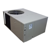
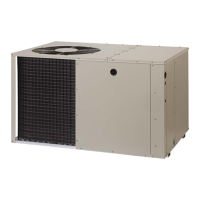
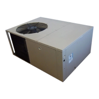
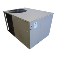
The provided document is a user's manual and installation instructions for a Single Package Air Conditioner, specifically the P3RX Series - Export Models, manufactured by Nordyne.

Function Description

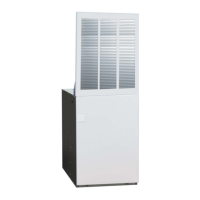
The Nordyne P3RX Series Single Package Air Conditioner is designed for outdoor installation and provides cooling and dehumidification for manufactured homes. It integrates the evaporator coil, condenser coil, compressor, and fan components into a single outdoor unit, simplifying installation and connection to the home's duct system. The system works by drawing return air from the home, passing it through the evaporator coil where it is cooled and dehumidified, and then delivering the conditioned air back into the home via supply ducts and registers.

Important Technical Specifications

The manual provides refrigerant charging tables for 2 Ton, 2-1/2 Ton, 3 Ton, 3-1/2 Ton, 4 Ton, and 5 Ton units, indicating various suction and discharge pressures, and discharge temperatures at different outdoor temperatures (70°F to 105°F). These tables are crucial for proper refrigerant charging and system performance.

Electrical Connections:

  • High Voltage: The unit requires a branch circuit disconnect of adequate size per NEC, located within sight of the unit. For single-phase models, L1 and L2 connect directly to the contactor. For three-phase models (380V/420V or 208V/230V), L1, L2, and L3 connect directly to the 3-pole contactor. The unit must be grounded using the green grounding screw in the control panel.
  • Low Voltage: 24V control wires are routed through a sealing grommet. The manual includes wiring diagrams for Single Phase (703772B), Three Phase 380V/420V (703809B), and Three Phase 208V/230V (703841B) units, detailing connections for the thermostat (R, Y, G, W terminals), blower relay, compressor contactor, and transformer.
  • Overcurrent Protection: The smallest fuse or breaker size that permits normal operation without nuisance trips is recommended for maximum equipment protection. Time-delay type fuses are specified to prevent nuisance trips during startup.

Ducting System:

  • Supply Duct: 12 inches in diameter for all units.
  • Return Duct: 12 inches or 14 inches in diameter, depending on unit size (refer to table on page 5).
  • Minimum Unit Clearances: 12 inches from the coil, and 6 feet above the fan. A minimum of 24 inches is required from the side of the unit with the condenser coil.

Condensate Drain:

  • A 3/4-inch condensate fitting extends from the side of the unit. A P-trap, supplied with the unit, must be installed to prevent water collection inside the unit and ensure proper drainage.

Usage Features

Operating Instructions:

  • Turning On: For a heating/cooling thermostat, set the system switch to "Cool" and the thermostat to the desired temperature. For separate heating and cooling thermostats, ensure they are interlocked (as shown in Figure 1) to prevent simultaneous operation. Set the heating thermostat to its lowest setting, turn the cooling thermostat "On" (if applicable), and set it to the desired temperature.
  • Turning Off: For a heating/cooling thermostat, set the system switch to "Heat" or "Off" and the thermostat to the desired heating temperature. For separate thermostats, turn the cooling thermostat "Off" or to its highest setting. For extended periods or winter shutdown, turn off the main power to the air conditioner.
  • Thermostat Location: The thermostat should be located on an inside wall, approximately five feet from the floor, away from drafts, direct sunlight, lamps, kitchen ranges, or direct airflow from supply registers.

System Operation Rules:

  • Always run the system with a clean filter to prevent coil clogging.
  • Set the thermostat to a comfortable level and leave it to control the system.
  • Understand that cooling takes longer than heating; temperature drops will be gradual.

Maintenance Features

Regular Checks:

  • Filters: Check filters every ten days in summer. Washable filters can be cleaned with a mild solution of detergent and water; non-washable filters should be replaced.
  • Outdoor Condenser Coil: Keep the outdoor condenser coil clean by hosing it down when dirty.
  • Professional Servicing: It is recommended to have a serviceman check the system at the start of each air conditioning season to ensure proper operation, clean/change filters, and make necessary adjustments.

Troubleshooting (If the unit isn't working):

  • Check fuses or circuit breakers.
  • Verify thermostat settings (desired temperature, "Cool" mode).
  • Ensure the return register is not covered and the filter is clean for free airflow.
  • Check the outdoor condenser coil for cleanliness and obstructions.
  • If problems persist, contact the nearest distributor.

Pre-Start Check List (Installer/Serviceman):

  • Verify the unit is level or slightly slanted towards the drain.
  • Ensure free airflow to and from the condenser (one-foot clearance around the coil, six feet above the fan).
  • Confirm correct wiring according to diagrams and codes.
  • Check all wiring connections for tightness.
  • Verify the condenser fan turns freely.
  • Confirm proper sizing of overcurrent protection.
  • Check correct thermostat wiring and location.

Start-Up Procedure (Installer/Serviceman):

  • Set the system switch to "OFF" and the thermostat dial to its highest setting.
  • Turn on the power supply.
  • Set the system switch to "ON" or "COOL" and the temperature setting below room temperature. Verify indoor blower, compressor, and outdoor fan operation.
  • Adjust discharge air grilles and balance the system.
  • Verify no air leaks in ductwork.
  • Confirm condensate drain is properly installed and functioning.
  • Set the thermostat higher than room temperature to stop the unit.
  • If using a combination heating-cooling thermostat, check furnace operation.
  • Verify furnace controls and burners/heating elements operate correctly.
  • Instruct the owner on unit operation, filter servicing, and thermostat operation.

Nordyne P3RX Series Specifications

General IconGeneral
BrandNordyne
ModelP3RX Series
CategoryAir Conditioner
LanguageEnglish

Related product manuals