Start Up | 22
Installation Check
Before turning on power to the RH inspect the installation to insure that it was carried out
correctly. Refer to, to RH Pre-Start Up Checklist on page 26, and to the chapter on installation.
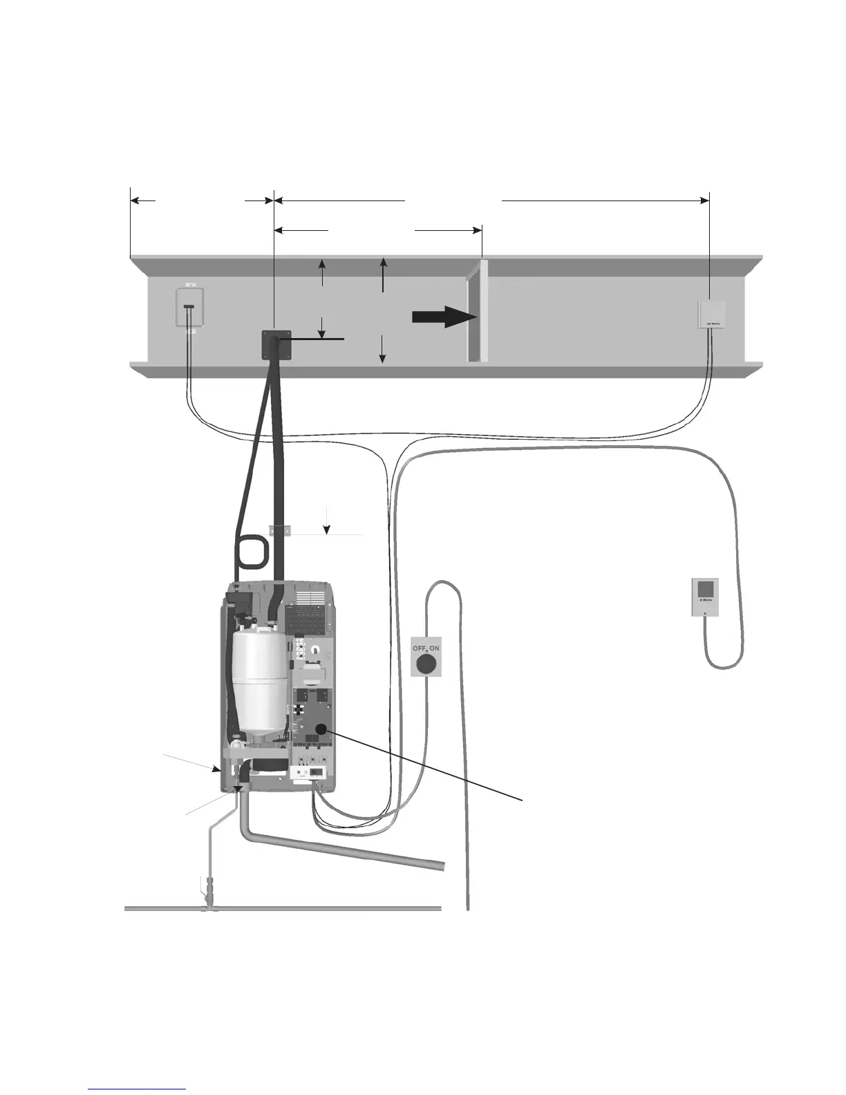
Figure 23: Installation Check
Steam Line
- Adequate slope
- No restrictions
- no kinks (hose)
- Condensate
traps on long
runs
P Trap with
12 in (30 cm)
min drop
.
Fused
Disconnect
Correct
voltage /
amps / phase
per spec label.
On/Off
Controls
(Air Proving)
in series
between
terminal
1 and 2
10 ft (3 m) min.
Humidity Control
- Wired to Term 4.
- n series between
term 1 and 2.
location which
represents
humidified
space (no drafts,
not by door, not by
diffuser).
I
Modulating
On/Off
- in return duct or
Air Gap
Not Plastic Drain,
Not to sink.
High Limit
On/Off
- In series between
terminal1and 2
Modulating
- Wired to termina 4.
Mounting
- Unit Level
- Screws into
structural
member
Spec Label
4 ft (1.2 m) min.
Filter, bend or
any other
obstruction.
1/2 in line min to within 4 ft (1.2 m)
30-80 PSI
2 x duct height
from fan or
transition
2/3 duct
height
12 in.
(30 cm)
min.
Note: if a modulating control
is connected to the RH
then jumper J10 must
be removed.