EasyManua.ls Logo

Nortech PD17x - 6 Configuration; PD171 Enhanced Detector - Order Number 307 FT0103; PD172 Enhanced Detector - Order Number 307 FT0101

Default Icon
31 pages
Print Icon
To Next Page IconTo Next Page
To Previous Page IconTo Previous Page
Loading...
307UM0100_01 May 2016 PD17x User Manual Page 18 of 31
6. Configuration
WARNING: 1. The connector PIN assignments vary from model to model.
Refer to the label on the side of the unit for connector PIN
assignment.
WARNING: 2. The wiring harness is only rated for SELV voltages (less than
60V DC or 42V AC). If the relays are to switch higher
voltages use CE LVD approved 11 pin sockets.
WARNING: 3. The wiring harness wire colour to PIN No. assignment
shown below only applies to wiring harness Part No.
301FT0041. Other wiring harnesses will have different wire
colour to PIN No. assignments.
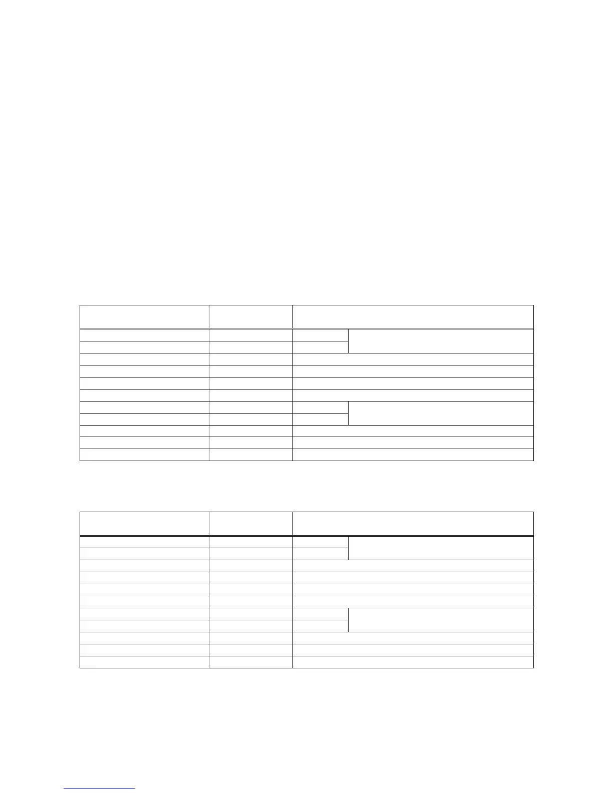
6.1 PD171 Enhanced Detector - Order number 307FT0103
11-pin connector wiring for PD171 DETECTOR - Order number 307FT0103
301FT0041 Wiring Harness
Wire COLOUR
11 PIN Connector
Pin No.
FUNCTION
Red
1
Live
Power supply
120V AC ± 10% 50/60Hz
Black
2
Neutral
Grey
3
N/O Pulse Contact
Violet
4
Common Pulse Contact
Yellow
5
N/O Presence Contact
Brown
6
Common Presence Contact
Blue
7
Loop
Twist this pair
Blue
8
Loop
Green/Yellow
9
Earth
Pink
10
N/C Presence Contact
White
11
N/C Pulse Contact
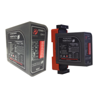
6.2 PD172 Enhanced Detector - Order number 307FT0101
11-pin connector wiring for PD172 DETECTOR - Order number 307FT0101
301FT0041 Wiring Harness
Wire COLOUR
11 PIN Connector
Pin No.
FUNCTION
Red
1
Live
Power supply
230V AC ± 10% 50/60Hz
Black
2
Neutral
Grey
3
N/O Pulse Contact
Violet
4
Common Pulse Contact
Yellow
5
N/O Presence Contact
Brown
6
Common Presence Contact
Blue
7
Loop
Twist this pair
Blue
8
Loop
Green/Yellow
9
Earth
Pink
10
N/C Presence Contact
White
11
N/C Pulse Contact

Related product manuals