307UM0100_01 May 2016 PD17x User Manual Page 8 of 31
3. Operating Procedure
3.1 Hardware setup
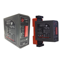
The PD17x Series single channel parking detector is designed to be DIN rail mounted, with the controls and visual
indicators at the front, and wiring at the rear of the enclosure. The power, loop and relay outputs are connected to the
11 pin relay base at back of the housing.
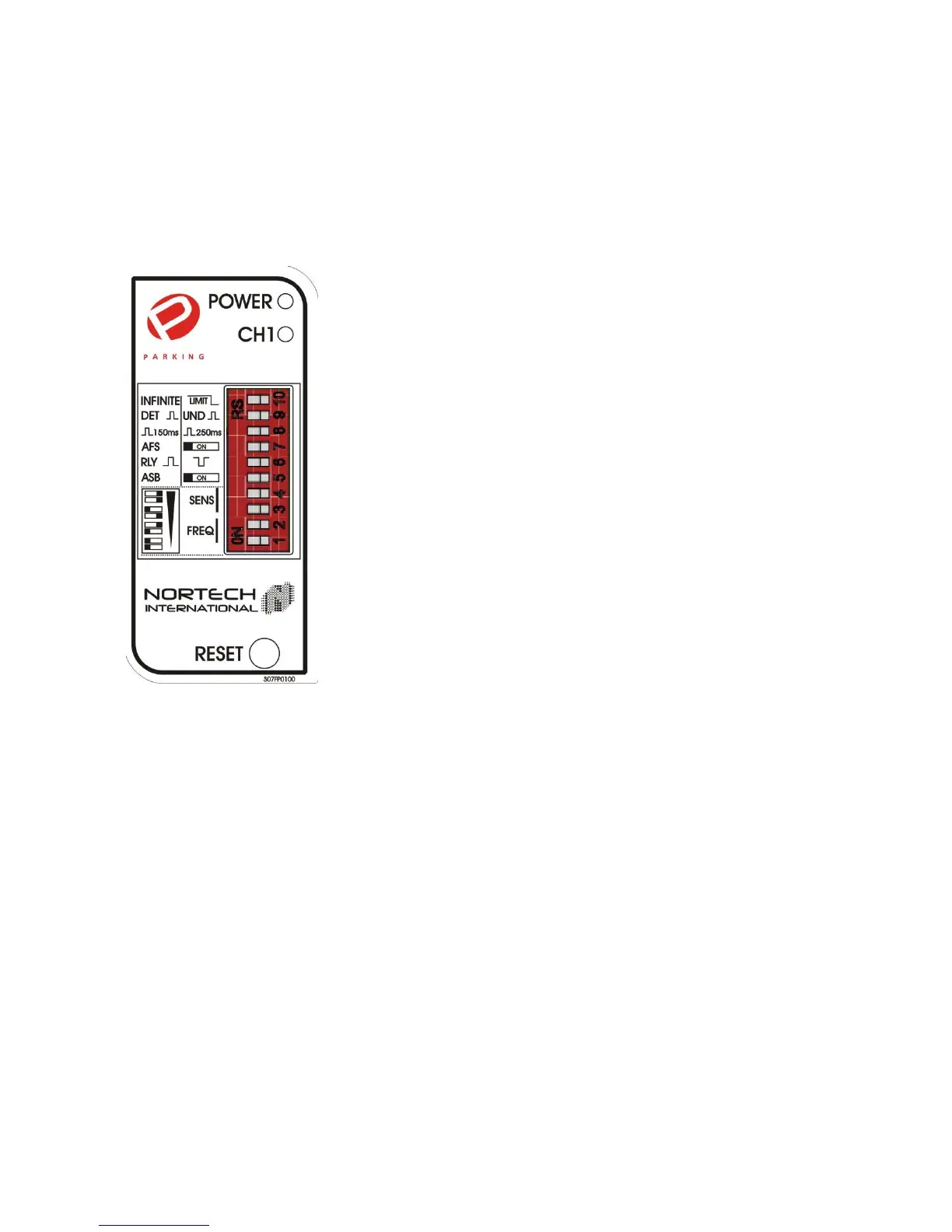
3.2 DIP Switch Selections
3.2.1 Presence Time (switch 10)
The presence setting determines how the detector will track a detect. There are two
modes, permanent presence and limited presence.
Permanent presence mode is aimed at maintaining the presence of a vehicle over
the loop by continuously compensating for all environmental changes. This is used
in situations where safety is involved and the detector is required to maintain the
detect until the vehicle leaves the loop.
Limited presence is aimed at limiting the presence of a vehicle over the loop. This is
used in situations where statistics or control is involved and a vehicle parked over
the loop should not prevent continued operation. The presence time is related to
the size of the detect. Typically a 1% ∆L/L will timeout after approximately 1 hour.
3.2.2 Pulse on Detect or Un-detect (switch 9)
The user can select the detector to pulse on detect, as a vehicle enters the loop or
pulse on un-detect, as the vehicle exits the loop.
3.2.3 Pulse Width (switch 8)
The pulse width of the relay can be selected to be either 150ms or 250ms.
3.2.4 Automatic Frequency Selection (AFS) (switch 7)
This setting allows the detector to briefly evaluate all five frequency bands and
select the best operating frequency available. The tuning time with AFS switched on
can range between 5 to 20 seconds. With AFS switched off, the frequency can be
selected manually.
3.2.5 Fail-safe or Fail-secure (switch 6)
The relay output operation of the presence relay can be switched between fail-safe and fail-secure via the DIP switches.
In fail-safe, the output is the same in detect as it is with no power applied to the unit. Related to an access control
situation, this is used where the loss of power must not lock people out. Either a valid detect situation, or a power failure
/ fault will provide a signal.
In fail-secure, the output is the same in un-detect as it is with no power applied to the unit. Related to an access control
situation, this is used where the loss of power must not allow free entry. Only a valid detect situation will provide a
signal.
3.2.6 Automatic Sensitivity Boost (ASB) (switch 5)
ASB is a mode which alters the un-detect level of the detector, and can be toggled on or off via the DIP switches. ASB
causes the sensitivity level to be boosted to a maximum on detection of a vehicle, irrespective of the current sensitivity
level, and maintained at this level during the entire presence of the vehicle over the loop. When the vehicle leaves the
loop and the detection is lost, the sensitivity level reverts to the pre-selected level. This is typically used for vehicles
with high beds, or vehicles towing trailers, where it is important to not lose the detect over the entire length of the
vehicle.