14
circuit protection of the internal wiring and serve as
over-current protection of the supply wiring and may
Overcurrent protection of the supply wiring is
Table 6 (page 19).
It is recommended that the line voltage (240 VAC) to
the furnace be supplied from a dedicated branch circuit
containing the correct fuse or circuit breaker for the furnace.
For minimum circuit ampacity and maximum over-current
protection, see Table 6. See unit wiring diagrams (Figure
23, Figure 24, Figure 25, & Figure 26) for wiring details.
Electrical components are shown in Figure 19 (page 16).
Supply circuit requirements are listed below:
• -010model is factory-wired forsingle-branch supply
circuit only.
• -012modelsarefactory-wiredforsingle-branchsupply
circuit (single-circuit kit factory installed). Dual-branch
circuit can be used by removing factory-installed
single-circuit kit. See Figure 17.
• -015,-017,-020and-023modelsarefactory-wiredfor
dual-branch supply circuit. Single-branch circuit can
be used by installing optional single-circuit kit.
Connecting Supply Service Wires
Power entrance for all models may be through the right
side or through the bottom of the unit.
1. Remove right-hand control panel (when viewing in
downflow position).
2. Locate power supply knockouts in side of unit and in
bottom of unit. Remove appropriate plug(s) or knockout
opening applicable to selected wire size(s).
WARNING:
To avoid personal injury or property damage,
make certain that the motor leads cannot
come into contact with non-insulated metal
components of the unit.
3. Install listed cable connector(s) in opening(s). If metal-
sheathed conduit is used for incoming power line(s),
provide an approved metal clamp on conduit and secure
it in entrance knockout.
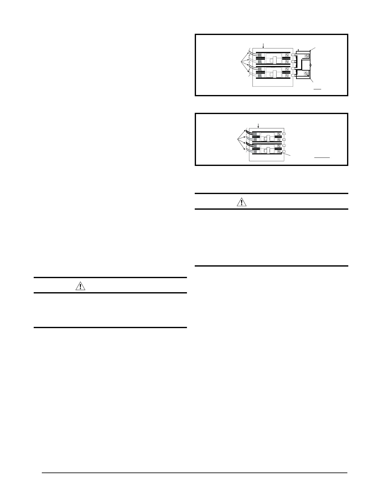
4. Insert supply service wire(s) through cable connector(s)
and connect wires to circuit breakers (Figure 17 & Figure
18). NOTE: To install single-circuit kit, perform step 5.
If single-circuit kit installation is not needed, go to step
6.
5. To install optional single-circuit kit:
a. Loosen lugs at supply side of circuit breakers.
b. Remove cover from single-circuit kit (if supplied).
c. Insert metal buss bars of kit into lugs of circuit
breaker.
d. Tighten lugs securely (45 in.-lbs. recommended).
6. Connect service ground wire(s) to grounding lug(s)
provided. One ground is required for each supply circuit
used. See Figure 19 (page 16).
Grounding
WARNING:
methods include electrical wire or conduit
approved for ground service. Do not use gas
piping as an electrical ground!
Thermostat / Low Voltage Connections
• Thefurnaceisdesignedtobecontrolledbya24VAC
thermostat. The thermostat’s wiring must comply with
the current provisions of the NEC (ANSI/NFPA 70)
and with applicable local codes having jurisdiction.
• The thermostat should be mounted about 5 feet
above the floor on an inside wall. DO NOT install the
thermostat on an outside wall or any other location
where its operation may be adversely affected by
radiant heat from fireplaces, sunlight, or lighting
fixtures, and convective heat from warm air registers
or electrical appliances. Refer to the thermostat
manufacturer’s instruction sheet for detailed mounting
information. See Figure 22 (page 18) for typical
thermostat connections.
• For proper indoor blower operation and temperature
rise, the E4 electric furnace requires that the system
thermostat be configured NOT to call for the indoor
blower to operate in the heating mode. Refer to your
specific thermostat installation instructions for details
on the heating mode indoor blower configuration.
• The E4 series electric furnaces incorporate an
integrated control. The thermostat’s 1st stage
compressor signal, Y, must be connected to the
YELLOW control wire at the furnace to enable the
indoor blower off-delay in the cooling mode.
OPTIONAL
SINGLE CIRCUIT
ADAPTOR KIT
CIRCUIT BREAKER
BRACKET
60A
60A
ONON
OFF
OFF
CIRCUIT BREAKER
WIRE ASSEMBLIES
(FACTORY INSTALLED)
SUPPLY SERVICE WIRE
CONNECTION WITH SINGLE
CIRCUIT ADAPTOR KIT
Figure 17. Optional Single Circuit Adaptor Kit
Figure 18. Installation of Supply Service Wires
60A
60A
ON
ON
OFF
OFF
CIRCUIT BREAKER
WIRE ASSEMBLIES
(FACTORY INSTALLED)
CIRCUIT BREAKER
BRACKET
SUPPLY SERVICE WIRE
CONNECTION WITHOUT SINGLE
CIRCUIT ADAPTOR KIT
 Loading...