215658-B
12
Connection requirements
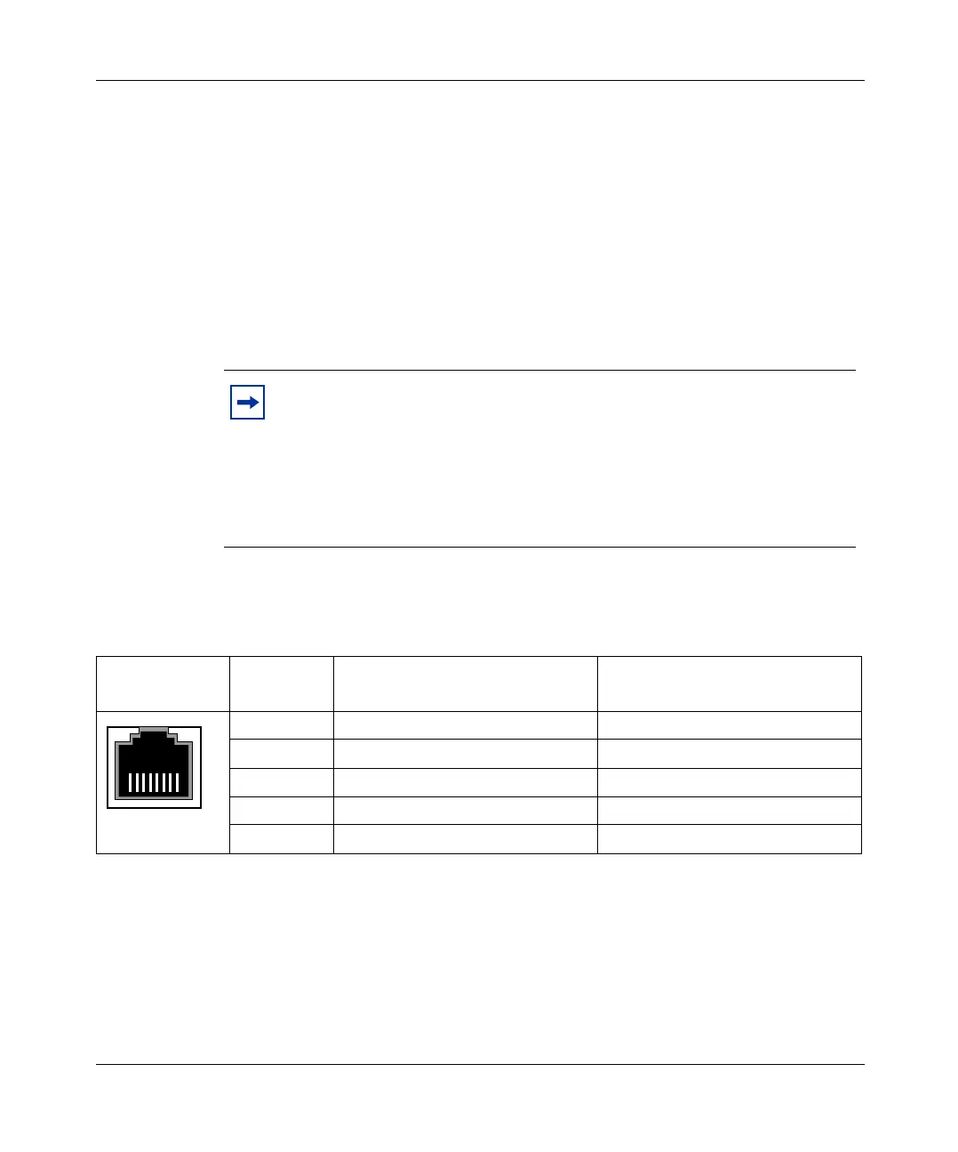
Figure 2 shows the connector pin assignments in the 10/100 BASE-T port.
Required cables:
10/100BASE-T ports: For 10 Mb/s operation: Category 3, 4, or 5 UTP cable with an RJ-45 connector.
For 100 Mb/s operation: Category 5 UTP cable with an RJ-45 connector.
For 1000 Mb/s operation: Category 5 UTP cable with an RJ-45 connector.
Console Port: Serial Cable with DB-9 female connector on one end.
Note: The maximum length for the console port cabling is 25 feet (8.3m).
SFP GBIC ports: Varies with the installed SFP GBIC; refer to the documentation that was
shipped with the SFP GBIC for specifications.
Note: When Autonegotiation is enabled, the BayStack 425 switch
automatically provides the proper MDI/MDI-X connection on the RJ-45
ports, thereby eliminating the need for crossover cables. When
Autonegotiation is disabled, the RJ-45 ports provide an MDI-X
connection, which allows end-station equipment to be connected using
straight-through cables. To connect other MDI-X port devices, such as
another switch or a hub, a crossover cable must be used.
Figure 2 Pin assignments in the 10/100 BASE-T port
Connector Pin Number
Signal for 10/100BASE-T MDI
Configuration
Signal for 10/100BASE-T MDI-X
Configuration
1 Output transmit data + (TX+) Input receive data + (RX+)
2 Output transmit data - (TX-) Input receive data - (RX-)
3 Input receive data + (RX+) Output transmit data + (TX+)
6 Input receive data - (RX-) Output transmit data - (TX-)
4, 5, 7, 8 Not used
87654321
9464EA
book.book Page 12 Thursday, July 29, 2004 10:07 PM