215658-B
18
Checking LEDs
Refer to the illustration and tables that follow for descriptions of the LEDs on the
BayStack 425 switch. The tables describe LED operation for a switch that has
completed its power-on self-tests.
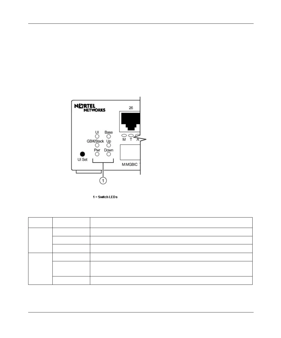
Figure 7 shows the BayStack 425 switch LED display panel.
Figure 7 BayStack 425 LED display panel
Table 6 LEDs on the BayStack 425
Label Color/Status Meaning
UI
Green The switch is operating normally.
Amber A flash error occurred.
Off The switch is inactive.
Base
Green This switch is the active base unit in the stack.
Amber This switch is configured as the base unit, but is not currently the active base
unit.
Off This switch is not the base unit, or is in a stand-alone configuration.
book.book Page 18 Thursday, July 29, 2004 10:07 PM