Installing the BayStack 425 Switch
17
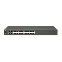
Front panel
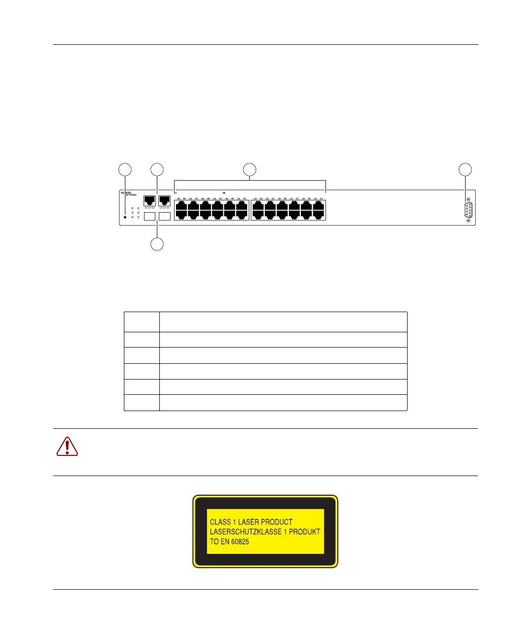
Figure 6 shows the configuration of the front panel on the BayStack 425. Table 5
describes the components on the front panel.
Figure 6 BayStack 425 front panel
Table 5 Components of the BayStack 425 front panel
Item Description
1 User interface reset button (not supported in this release).
2 10/100/1000BaseT (copper) port 25 and 26
3 Gigabit Interface Converter (GBIC) ports 25 and 26
4 10/100BaseT ports 1 to 24
5 Console port
Warning: Fiber optic equipment can emit laser or infrared light that can injure your eyes.
Never look into an optical fiber or connector port. Always assume that fiber optic cables
are connected to a light source. (For translations of this statement, see page 31.)
BaseUI
UI Set
2526
M:MGBIC A:ActivityT:1000T
M
LED Status - Amber:10Mps Green:100 Mps Blink:Activity
GBK/Stack Up
Pwr Down
Console
BayStack 425-24T Switch
TM
BayStack
T A M T A
1 2 3 4 5 6 7 8 9 10 11 12
LED Status - Off:Half Duplex Green:Full Duplex
13 14 15 16 17 18 19 20 21 22 23 24
BayStack 425-24T Switch
41 52
3
11108EA
8769EA
book.book Page 17 Thursday, July 29, 2004 10:07 PM