hexagon-the
tappet stem or push
rod-and
the second on the locking nut.
Tum
the top
hexagon-the
tappet head
or
push rod
adjuster-in
the desired direction,
and when the correct clearance is obtained,
tighten locking nut.
Check clearance after tightening locking nut.
17.
REMOVAL
OF
PISTON
AND
RINGS.
Remove cylinder barrel (Para. 9).
Remove one circlip and the gudgeon pin.
Gudgeon pin is a nmning fit
in
the piston
and small end bush.
Mark piston to ensure
it
is
fitted the same
way when replacing.
Remove rings from piston.
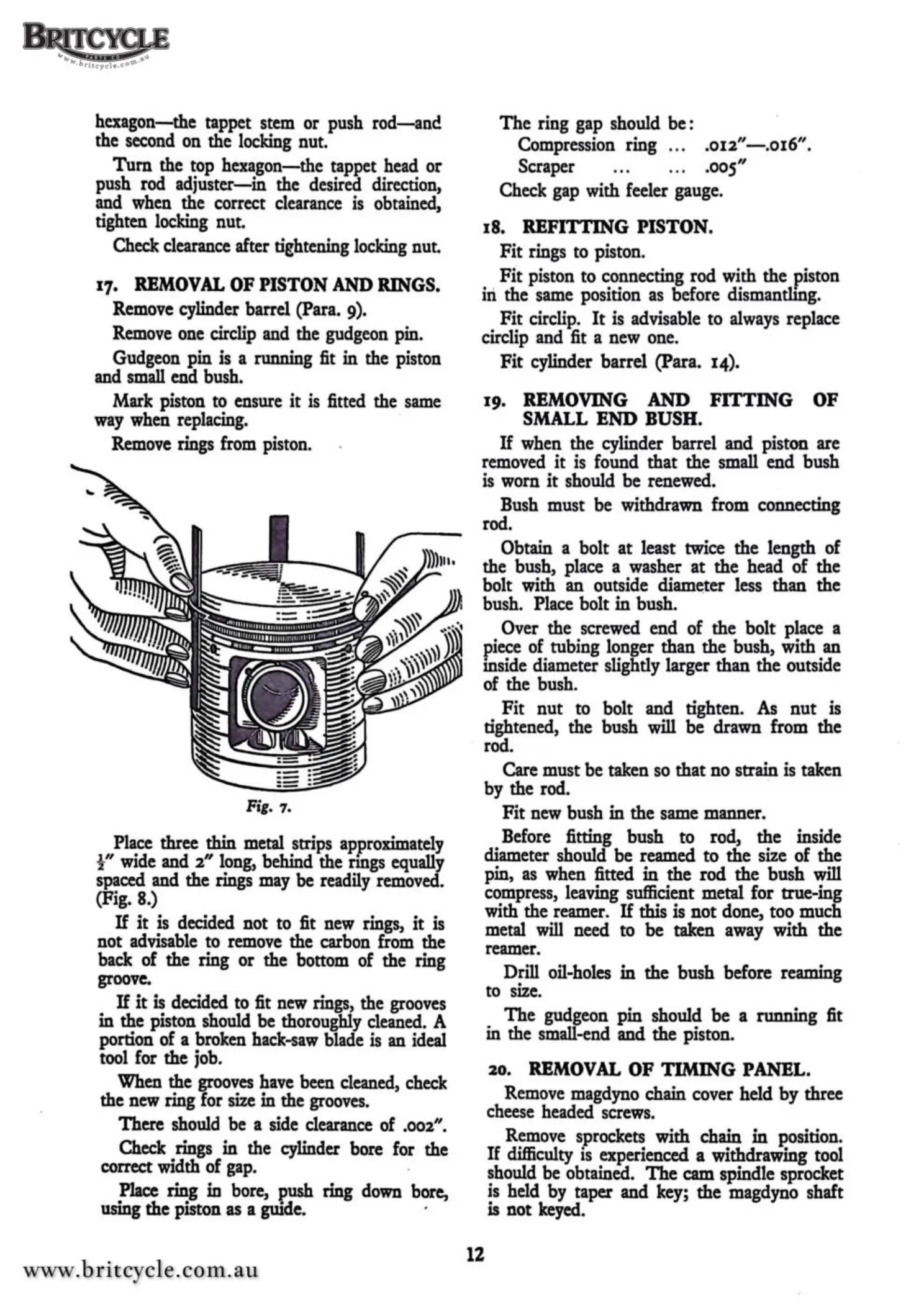
Fig.
1.
Place three thin metal strips approximately
½"
wide and
2"
long, behind the rings equally
spaced and the rings may be readily removed.
(Fig.
8.)
If
it
is
decided not to fit new rings,
it
is
not advisable to remove the carbon from the
back of the ring or the bottom of the ring
groove.
If
it
is
decided to fit new rings, the grooves
in
the piston should be thoroughly cleaned. A
portion of a broken hack-saw blade
is
an ideal
tool for the job.
When the grooves have been cleaned, check
the new ring for size
in
the grooves.
There should be a side clearance of
.002".
Check rings
in
the cylinder bore for the
correct width of gap. .
Place ring in bore, push ring down bore,
using the piston as
a guide. ·
The
ring gap should be :
Compression ring . . .
.012"
-.016".
Scraper .oos"
Check gap with feeler gauge.
18.
REF
G PISTON.
Fit
rings to piston.
Fit
piston to connecting rod with the piston
iri
the same position as before dismantling.
Fit
circlip.
It
is advisable to always replace
circlip and fit a new one.
Fit
cylinder barrel (Para. 14).
19.
REMOVING
AND FITTING
OF
SMALL
END BUSH.
If
when the cylinder barrel and piston are
removed
it
is
found that the small end bush
is
worn
it
should be renewed.
Bush must be withdrawn from connecting
rod.
Obtain a bolt
at
least twice the length of
the bush, place a washer
at
the head of the
bolt with an outside diam~ter less than the
bush. Place bolt
in
bush.
Over the screwed end of the bolt place a
piece of tubing longer than
the
bush, with an
inside diameter slightly larger
than
the outside
of the bush.
Fit
nut
to bolt and tighten. As
nut
is
tightened, the bush will
be
drawn from the
rod.
Care must be taken so that no strain is taken
by the rod.
Fit
new bush
in
the same manner.
Before fitting bush to rod,
the
inside
diameter should
be
reamed
to
the
size of the
pin, as when fitted
in
the
rod
the
bush will
compress, leaving sufficient metal for true-ing
with the reamer.
If
this is
not
done, too much
metal will need to
be
taken away with the
reamer.
Drill oil-holes
in
the
bush before reaming
to size.
12
The
gudgeon
pin
should
be
a ninning fit
in the small-end and
the
piston.
20.
REMOVAL
OF
TIMING
PANEL.
Remove magdyno chain cover held
by
three
cheese headed screws.
Remove sprockets with chain
in
position.
If difficulty
is
experienced a withdrawing tool
should be obtained.
The
cam spindle sprocket
is held by taper and key;
the
magdyno shaft
is not keyed.
 Loading...