simple as to require no instructions for their
dismantling or assembly.
The pivot bolts have shoulders machined
on them, allowing the nuts on the bolts to
be tightened while allowing clearance for
easy
movement of the lever.
To
remove the clutch cable from the lever,
tum
the clutch operating arm on the clutch
worm by other means than the cable, and
the nipple can be removed from the arm, and
inner and outer cables can be removed from
the lever.
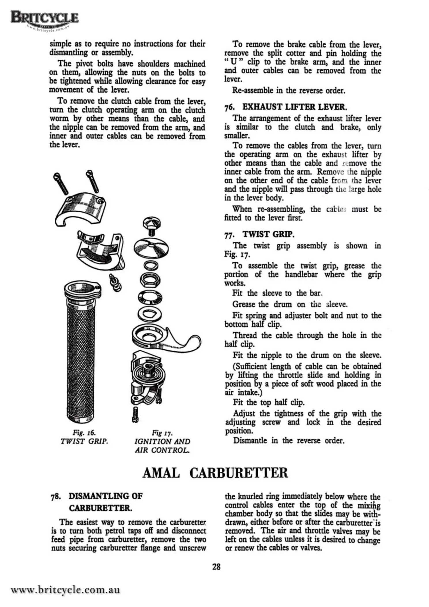
Fig.
16.
TWIST
GRIP.
I
Fig 17.
IGNITION
AND
AIR
CONTROL.
To
remove the brake cable from the lever,
remove the split cotter and pin holding the
" U " clip to the brake arm, and the inner
and outer cables can be removed from the
lever.
Re-assemble in the reverse order.
76.
EXHAUST
LIFTER
LEVER.
The
arrangement of the exhaust lifter lever
is similar to the clutch and brake, only
smaller.
To
remove the cables from the lever, turn
the operating arm on the exhaust lifter by
other means than the cable
an
d c
move
the
inner cable from the arm. Remove the nipple
on the other end of the cable fro . the
lev
er
and the nipple
will
pass through the
la
rge hole
in the lever body.
When re-assembling, the
cab
le
: must be
fitted to the lever first.
77.
TWIST
GRIP.
The
twist grip assembly
1s
shown in
Fig.
17
.
To
assemble the twist grip, grease the
portion of the handlebar where the grip
works.
Fit
the sleeve to the bar.
Grease the drum on the s
leeve.
Fit spring and adjuster bolt and nut to the
bottom half clip.
Thread the cable through the hole in the
half clip.
Fit the nipple to the drum on the sleeve.
(Sufficient length of cable can be obtained
by lifting the throttle slide and holding in
position by a piece of soft wood placed in the
air
intake.)
Fit the top half clip.
Adjust the tightness of the grip with the
adjusting screw and lock in the desired
position.
Dismantle in the reverse order.
AMAL
CARBURETTER
78.
DISMANTLING
OF
CARBURETTER.
The
easiest
way
to remove the carburetter.
is to turn both petrol taps
off
and disconnect
feed
pipe from carburetter, remove the
two
nuts securing carburetter flange and unscrew
28
the knurled ring immediately below where the
control cables enter the top of the mixitig
chamber body
so
that the slides may be with-
drawn, either before or after the carburetter•
is
removed. The air and throttle
valves
may be
left on the cables unless it
is
desired to change
or renew the cables or
valves.