End
ftoat
on
exhaust cam spindle can only
be
properly checked when crankcase halves
are separated.
Tappets must
be
entered into tappet guides
from inside timing chest before the guides are
pressed into position.
This
necessitates a tubular drift to finally
force the guides home.
Tappet
guides are located radially by a peg
in
top of crankcase, which fits into a hole
in
tappet guide collar. Hole and peg should
be
as
nearly
in
alignment as possible before
pressing
or
tapping the guide into position.
Fit
half-time pinion to mainshaft and rotate
engine till crankpin is on T.D.C.
Fit
cam gears, meshing the marked teeth
with the appropriate markings on the pinion.
Fit
and tighten oil pump worm,
LEFT
HAND
thread, using punch or peg spanner.
Fit
oil pump, ensuring that
both
faces arc
quite clean and using a minimnm of jointing
compound to avoid the oil holes becoming
obstructed.
Check fibre washer on oil pump nipple
and
fit timing panel (Para. 21).
Time
magneto (Para. 22).
25.
OIL
PUMP.
The
oil pump is of the gear type.
It
is not
advisable to dismantle it.
When pump is removed from timing chest,
test for play
in
the spindle by pulling and
pushing
the
worm wheel.
Revolve spindle and place · fingers on the
oil holes and the action of the gears should
be
felt if the pump is in good condition.
When revolving pump, any foreign matter
obstructing the gears will
be
felt. Wash out
with paraffin.
26.
OIL
CONTROL
VALVE.
This
is fitted
in
a boss on the inside of the
riming panel.
It
is an assembly of a ball,
spring and adjusting screw.
The
adjustment
is set
at
the works and should not need any
attention.
The
control valve acts
as
a safety valve
in
the oil circuit. When the oil is cold, the oil
pressure
in
the circuit tends to become ex-
cessively high,
but
the excess of pressure lifts
the ball
fro~
!ts seat, allowing the oil to spray
on to the tlmll1g gears.
If for any reason this is dismantled, the
order
of
assembly
is-ball,
spring and adjuster
nut.
14
Tighten the
nut
home and
then
screw out
one and a half turns and lock with centre
punch.
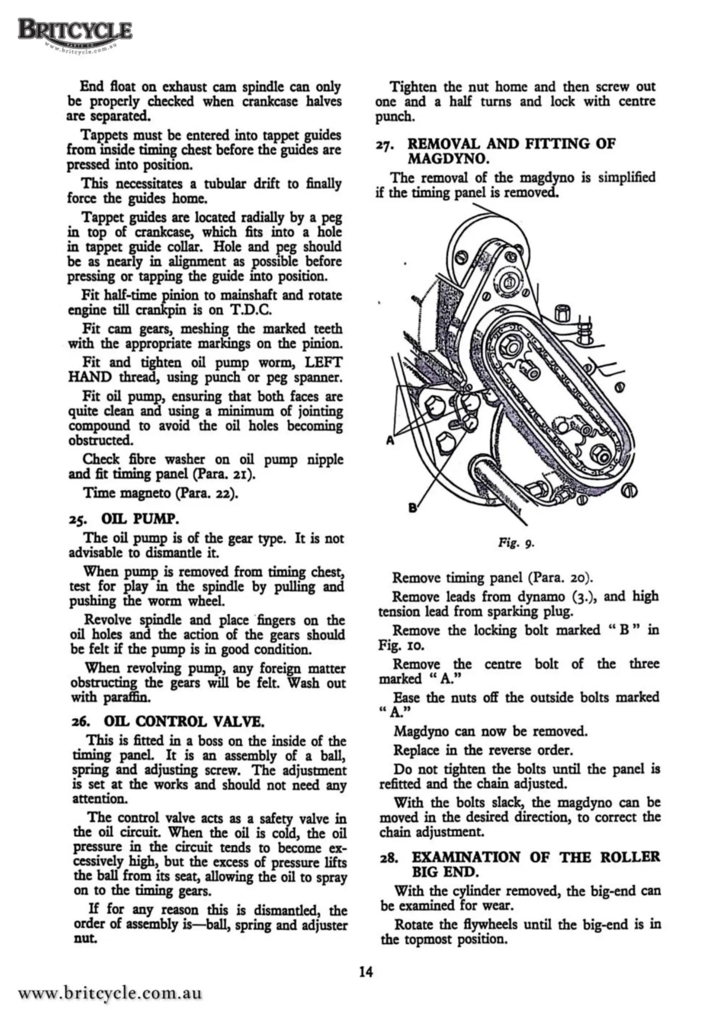
27.
REMOVAL
AND
FITTING
OF
MAGDYNO.
The
removal
of
the magdyno is simplified
if the timing panel is removed.
Fig. 9.
Remove timing panel (Para.
20
).
Remove leads from dynamo (3.), and high
tension lead from sparking plug.
Remove the locking bolt marked " B " in
Fig.
IO.
Remove the centre bolt
of
the three
marked " A."
Ease the nuts off the outside bolts marked
"A."
Magdyno can now
be
removed.
Replace
in
the
reverse order.
Do
not tighten the bolts until the panel is
refitted and the chain adjusted.
With the bolts slack, the magdyno can
be
moved
in
the desired direction, to correct the
chain adjustment.
28.
EXAMINATION
OF
THE
ROLLER
BIG
END.
With the cylinder removed,
the
big-end can
be examined for wear.
Rotate the flywheels until the big-end is in
the topmost position.
 Loading...