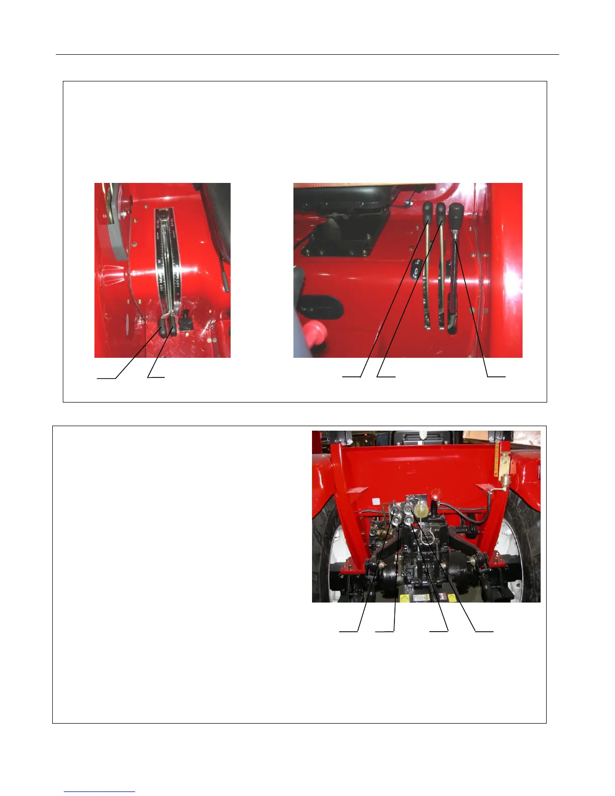
There are five levers that control the hydraulic system for farm implements towed by the tractor.
Control levers (A) and (B) are hydraulic float levers.
Control lever (C) controls the first hydraulic control loop (quick disconnects (A1) and (B1).
Control lever (D) controls the second hydraulic control loop (quick disconnects (A2) and (B2).
Control Lever (E) is the 3-point control lever.
A B C D E
Figure 2-27 Hydraulic Control Levers, Left and Right Sides of Driver
Shut off the engine.
Put the lifter in the lowering position.
Move the hydraulic output valve operation handle
forward and backward, in order to eliminate the
pressure in the hydraulic quick disconnect.
Remove the seal cover of the quick disconnects
to be used and clean the connectors.
Connect a hose with a male connector into the
female end of each quick disconnect on the valve.
Connect the other ends of these hoses to the oil inlet
and outlet of the double-acting oil cylinders on the
farm implement. The multiway valve has four
female connectors (A1, B1, A2, and B2). (A1) and
(B1) form the first group of the hydraulic output loop A1 B1 B2 A2
and are controlled by control lever (C). (A2) and (B2)
form the second group of the hydraulic output loop and
are controlled by control lever (D).
Figure 2-28 Multiway Valve