NOTE:The right and left pedal free path should be the same as the brake pedal free path.
Otherwise, in an emergency braking situation, the tractor may pull to one side. For safety sake, do a
braking test after making the adjustments. Interlock the right and left brake pedals. On a dry, flat road, hit
the brakes while running at high speed in a straight line. Get out and inspect the road surface for any trace
sliding. If the trace of the right and left wheels on the road is consistent, in a straight line and equally long,
that means that the adjustment is working properly.
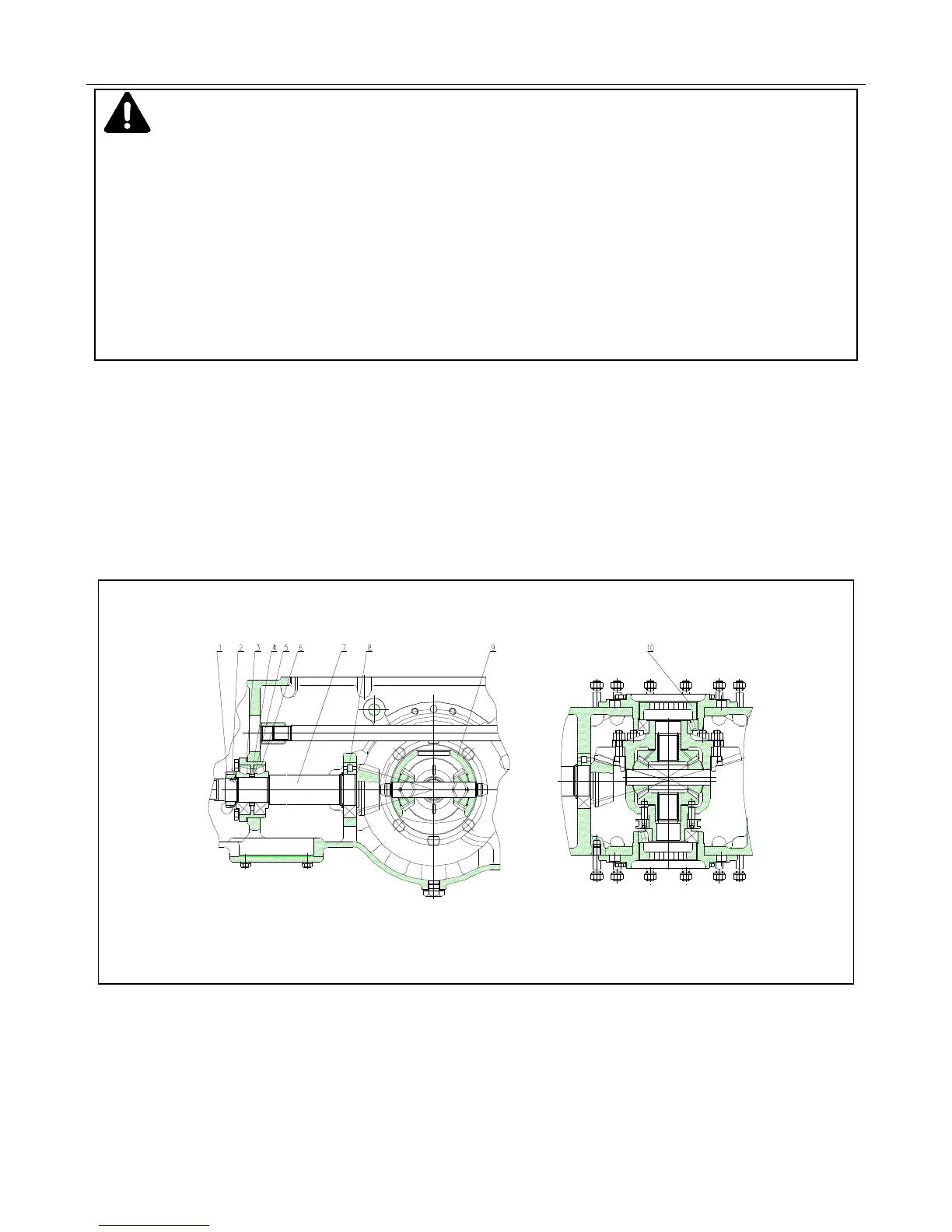
4.23.2 Rear Axle Structure and Adjustment
The rear axle is composed of a center drive, a differential, a differential lock and a PTO shaft (Figure 4-6).
4.23.3 Rear Axle Structure
Figure 4-6 Rear Axle Structure and Adjustment
1. Round Nut 2. Locking Gasket 3. Adjusting Gasket 4. Spacing Sleeve 5. Adjusting Gasket 6. Conical Roller Bearing
7. Bevel Pinion Shaft 8. Cylindrical Roller Bearing 9. Differential 10. Adjusting Nut