Appendicies
90
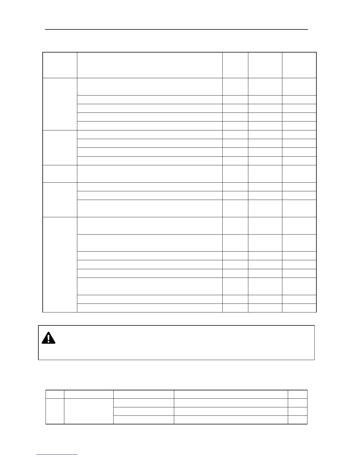
10.2 Tightening Torque Table of Major Bolts and Nuts (Table 10-2)
Table 10-2 Tightening Torque Table of Major Bolts and Nuts
Tightening
Torque
(ft- lbs)
Bolt connecting the engine with the gearbox
Bolt connecting the gearbox with the rear axle
Fixing bolt of the bearing of the differential
Fixing bolt of the large bevel gear
Bolt joining the housing of the drive shaft and the rear axle
Steering
and
Running
Systems
Bolt joining the hub and web of the driving wheel
Bolt joining the front driving wheel and the hub and web
Bolt joining the front driving wheel and the hub and web
Bolt at the steering ball joint
Bolt connecting the diesel engine to the frame
Hydraulic
Suspension
System
Bolt joining the housing of lifter and the rear axle
Bolt joining the oil cylinder end and the lifter housing
Bolt joining the brace of the upper drag link
and the rear axle housing.
Bolt joining the driven gear of the
front differential assembly and the differential
Bolt joining the housing of
left semiaxle and the right semiaxle
Bolt joining the housing of tee joint and the upper cover
Bolt joining the housing of final drive and the lower cover
Bolt joining the housing of final driver and the cover
Bolting that joins the steering arm-busher subassembly
and the housing of the final drive
Bolting that connects the diesel enige to the bracket
Bolt connecting the swing base assembly to the brake
NOTE: A tolerance of ±10% is permitted for the torques in the table.
WARNING: When tightening the major bolts and nuts on the tractor, torque wrenches must be used
to avoid reductions in tractor performance and injury.
10.3 Reinforced O-Ring Seal Specifications (Table 10-3)
Table 10-3 Reinforced O-Ring Seal Specifications
Rear end of the power output rear axle
Where the steering knuckle meets the hub
Seal of the transfer case