NOVATECH INSTRUMENTS 13 409C Manual Rev 1.12
10-bit digital-to-analog converters. The analog signals
from these converters are filtered by differential 7th-
order elliptical low pass filters, amplified and sent to
the 409C output connectors.
5.3 Maximum Frequency. The 409C theoretical out-
put frequency is limited to a maximum of 1/2 the sys-
tem clock frequency. While it is possible to generate an
output near 50% of the system clock, the distortion
would be unacceptable. For this reason, the 409C fre-
quency output is limited to 171MHz by 7th-order ellip-
tical low pass analog filters on all four output channels.
5.4 External Filters. External filters are NOT needed
when using the internal clock or the internal clock in
combination with the /R option. However, if you are us-
ing an external reference or direct clock you may need an
external filter. For best performance, set the corner fre-
quency at 40% or less of your synthesizer clock frequen-
cy. The synthesizer clock frequency can be displayed by
sending the “q” command after having entered the Fr or
Fd parameters and sending the ‘C e’ or ‘C d’ command.
6.0 PERFORMANCE TEST
6.1 Setup. Install the 409C as directed in the Serial Oper-
ation part of Section 3. Connect your host controller and
operate the 409C per Section 4. The test limits assume a
stable environment of 18-28
o
C.
NOTE:
Allow the 409C to warm up for at least 15 minutes before
performing any measurements. For best results, the 409C
should be verified in its installed environment.
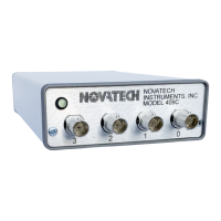
6.2 Test Equipment. See Table 6 for a list of recom-
mended test equipment to perform the following measure-
ments.
6.3 Verify Frequency Accuracy. To verify the frequency
of the 409C, set the output sequentially to each value in
Table 7. Connect the recommended frequency counter set
to 50Ω termination and 1 Hz resolution. Verify the limits
shown in Table 7. Test all channels to verify functionality
of all outputs. If you do not use an external reference for
the frequency counter, be sure to add the error of your
counter to the tolerance. (LSD = Least Significant Digit
on counter).
6.4 Sine Out Amplitude Verification. Set the frequency
of the 409C to 10 MHz. Connect the 409C to the oscillo-
scope set for 50Ω termination. Set the oscilloscope to
measure amplitude using at least 16 averages. Verify a
reading of 1Vpp ±0.25Vpp. Repeat for the other outputs.
6.5 Amplitude Level Test. Leave the output frequency
set to 10 MHz. Send the command “Vn 512” to each
channel, where “n” is your channel number being tested.
Verify that the amplitude on each channel decreases by
Item Minimum
Specification
Recommended
Oscilloscope 300 MHz
50Ω
Tektronix TDS3032B
50 Terminaon 50Ω +1% Tektronix
011-0049-01 or
HP53132A
Frequency
Counter
180 MHz HP53132A
Counter Time
Base
10 MHz
<+0.1 ppm
Novatech Instruments
Model 2960AR
External Clock 400 MHz Novatech Instruments
Table 6: Recommended Test Equipment
Frequency Tolerance
100 kHz + 0.15 Hz +1 LSD
1 MHz +1.5 Hz +1 LSD
10 MHz +15 Hz +1 LSD
30 MHz +45 Hz +1 LSD
50 MHz +75 Hz +1 LSD
100 MHz +150 Hz +1 LSD
170 MHz +255 Hz +1 LSD
Table 7: Frequency Test Points
 Loading...