NOVATECH INSTRUMENTS 2 409C Manual Rev 1.12
NOTE:
This manual applies to Model 409C with firmware
version 1.6 or higher.
1.0 DESCRIPTION
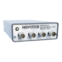
1.1 The Model 409C is a four-channel Direct Digital
Synthesized (DDS) Signal Generator in a small table top
case with serial control. The 409C provides four inde-
pendent, phase-synchronous sine wave output signals,
which can be set from 0.0 Hz (DC) to 171 MHz in 0.1
Hz steps.
1.2 The 409C System Clock can be an internal TCXO
oscillator or a user supplied external signal.
1.3 A Table feature enables users to store frequency,
phase, amplitude and dwell time. The 409C can then run
through the table automatically or step through it on
command from the serial port or from an external hard-
ware trigger.
1.4 A Frequency Sweep feature enables the user to gen-
erate automatically generated programmable sweeps .
1.5 The –AC option provides two rear panel mounted
SMA connectors that can also be used to trigger and syn-
chronize 409C output updates using external hardware
triggering.
1.6 The /R option converts the external clock input to a
10MHz reference input. This option enables locking to
and tracking an external 10MHz reference with no binary
round-offer errors. When this option is installed the accu-
racy and stability of the output are equal to those of the
reference.
2.0 SPECIFICATIONS
2.1 OUTPUTS
TYPES: Four independently programmable, phase syn-
chronous, sine wave outputs.
IMPEDANCE: 50Ω.
RANGE: 0.0 Hz to 171 MHz in 0.1 Hz steps (Sine out,
int. clock).
SINE AMPLITUDE: Programmable from 0.000 to 1.000
Vpp into 50Ω.
PHASE: Programmable from 0 to 359.99 degrees.
FLATNESS: ±3dB from 1 kHz to 150 MHz referenced
to amplitude at 35 MHz, full scale.
2.2 TABLE
Stores up to 14,250 rows containing frequency, phase,
amplitude, row number and a dwell time in non-volatile
memory. Each row can contain data for up to four out-
put channels.
2.3 CONTROL
Output frequencies (32-bits), amplitudes (10-bits) and
phases (14-bits) are controlled by sending commands
from the USB serial port or by executing rows saved in
the 409C table. All outputs and other settings can be
saved in non-volatile memory.
2.4 FREQUENCY ACCURACY AND STABILITY
Accuracy: <±1.5ppm at 10 to 40
o
C. Stable to an addi-
tional ±1pp m per year, 18 to 28
o
C. (Internal Clock)
2.5 EXTERNAL CLOCK IN
LEVEL: 0.2 to 0.5Vrms sine or square wave. 50Ω.
FREQUENCY: 10MHz to 125MHz with Clock set to
External Reference (C e) or 1MHz to 500MHz with
Clock set to direct input (C d).
2.6 INTERNAL CLOCK LOCKED TO EXTERNAL
10MHZ (/R OPTION): External clock must be 10 MHz,
±5ppm. Automatically detected. Internal clock is locked
to and tracks this value. Level must be 0.2 to 0.5 Vrms,
sine or square wave, 50Ω..
2.7 SPECTRAL PURITY
(Typical, 50Ω load, Clock set to Internal (C I), Output
set to full-scale)
Phase Noise: <-120dBc, 10 kHz offset, 10 MHz out.
Spurious:
<-60dBc below 10 MHz (typ. 300MHz span)
<-60dBc below 40 MHz
<-55dBc below 80 MHz
<-50dBc below 160 MHz
Harmonic:
<-65dBc below 1 MHz
<-55dBc below 20 MHz
<-45dBc below 80 MHz
<-35dBc below 160 MHz
(channel-channel isolation: <-60dBc)
 Loading...