NOVATECH INSTRUMENTS 3 409C Manual Rev 1.12
2.8 POWER REQUIREMENTS
+5.25Vdc (+5.0 to +5.5V)@<750mA.
2.9 SIZE
39mm H, 107mm W, 172mm L, not including connect-
ors.
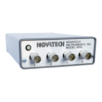
2.10 CONNECTORS
BNC for Sine Outputs and External Clock Input. Barrel
type 2.5mm center positive power receptacle for +5 volts
power input. USB 2.0 Type B female & 14 pin header
for logic I/O or Optional DB9.
2.11 LOGIC I/O (J8 AND –AC OPTION)
Voh >=2.4V and Vol <=0.4V when series terminated.
Output Rise and fall times <100ns.
2.12 OPTIONS
OPTION /R: Rear mounted BNC connector to accept
external 10MHz reference clock input. Disables rear
BNC use as a 1 to 500MHz clock input.
OPTION -AC: Provides two SMA connectors on the
rear panel for IOUD and TS signals.
OPTION /E: Adds SMA connector on the rear panel to
accept external clock input from 1 to 500MHz when /R
option is installed.
OPTION /RS232: Replaces rear panel USB connector
and J8 connector with DE9 connector. A USB to Serial
Adapter is provided with this option.
3.0 HARDWARE INSTALLATION
3.1 Power Connection. The input power is applied
through a 2.5mm center-positive power connector on the
rear panel. A solid green light on the front panel LED
indicates power is on.
3.2 Power Supply. The quality of your power supply
affects the performance of the 409C. The supply should
be free of ripple and noise (<100mV). Even though ex-
tensive filtering is used internal to the 409C, a quiet and
well regulated power supply will ensure optimum perfor-
mance. The supplied AC-adapter has been tested for
proper operation.
3.3 USB Serial Interface Installation. The 409C is typi-
cally controlled from a computer with a USB port. In
this configuration the user computer needs to have the
virtual COM port driver that is compatible with the USB
port on the 409C. This driver is made by Silicon Labs
and it is already installed on some computers. The Sili-
con Labs virtual COM port driver an be found at:
https://www.silabs.com/developers/usb-to-uart-bridge-
vcp-drivers.
The Silicon Labs VCPdriver for Microsoft windows is
included on the USB memory stick that comes with the
409C. To install this driver select the CP210xVCPIn-
staller… application that matches your computer and
run it.
3.4 /RS232 Option Installation. For 409C models with
the /RS232 option installed the 409C uses an RS323 seri-
al port, instead of the standard USB port. The /RS232
option includes the XCHIP-X RS232 to USB adapter
from FTDI. The virtual COM port driver for the XCHIP
-X is already installed in many computers. If it is not
installed then it can be downloaded at:
https://ftdichip.com/drivers/vcp-drivers/
Once the virtual COM port driver is installed you con-
nect the 409C to your computer using the provided cable.
The computer will then automatically create a virtual
COM port.
3.5 Virtual COM Port Settings. The USB and RS232
virtual COM port default settings are 115.2 kBaud, 8
bits, 1 stop bit, no parity and no hardware flow control.
NOTE:
The SOF8_409C windows application is included with
the 409C. This program has a “COM Port” menu where
you can view the available COM ports and select the
COM port that is connected to your 409C. The
SOF8_409C software automatically sets your selected
COM port to the 409C default COM port settings.
3.6 /RS232 Option Connector. For 409C models with
the /RS232 option, there is a DE9 connector with data
TO the 409C on pin 3; data FROM the 409C is on pin 2
and the COMMON return on pin 5. A six foot 9-pin
monitor extension cable is provided and allows direct
connection to the 409C without a null modem or gender
changer. The provided XCHIP-X USB adapter can be
connected to the extension cable for connecting to a USB
port.
 Loading...